
DC Molded Case Circuit Breakers (MCCB) · Technical Explainer
DC MCCB Pole Connection and System Voltage Verification
A DC molded-case circuit breaker can show several voltage ratings depending on how its poles are connected. A buyer cannot take the highest catalogue voltage and assume it applies to a different terminal route. The exact connection diagram, system grounding and fault-current path have to be checked together.

This guide focuses on reading manufacturer pole-connection evidence for DC MCCBs. It is not a wiring instruction for any unverified model. Final approval requires the project single-line, prospective fault study and current installation manual for the exact order code.
Why pole connection can change the DC rating
Interrupting direct current is different from interrupting AC because the current does not naturally cross zero every cycle. Some MCCB designs use more than one pole in series along a current path to achieve a documented voltage capability. Schneider Electric's DC MCCB documentation shows examples of series and parallel pole connections; those are product-specific schemes, not general permission to rewire another breaker.
The important object is the whole current path through the device. A breaker body with two, three or four poles may have its poles distributed across conductors or connected in series. The number of poles on the front label therefore does not tell you the full system-voltage capability or isolation behavior.
Ask which rating table applies to the proposed wiring, including rated operational voltage, breaking capacity and continuous current. A “per pole” voltage description may help explain the design but should not be multiplied by the buyer to invent a new device rating. Use only the manufacturer's stated complete-device rating for the exact configuration.
Begin with the system single-line
Mark the DC source, load, positive and negative conductors, grounding point and all possible paths by which a fault may be fed. Include normal and maintenance switching states. A battery and converter connected on opposite sides can create different current directions under charging, discharging and fault conditions.
Determine the maximum relevant voltage at the MCCB location, including charging or operating extremes. Do not use only the nominal bus voltage if another credible state is higher. Record the prospective short-circuit current at that location and the assumptions behind it. The selected breaker must have documented interruption capability at the same voltage and connection basis.
Clarify which conductors must be opened for protection and isolation. In a grounded system, the fault types and voltage seen by each pole path may differ from those in an isolated system. The manufacturer application diagram must match the project topology rather than merely look similar.
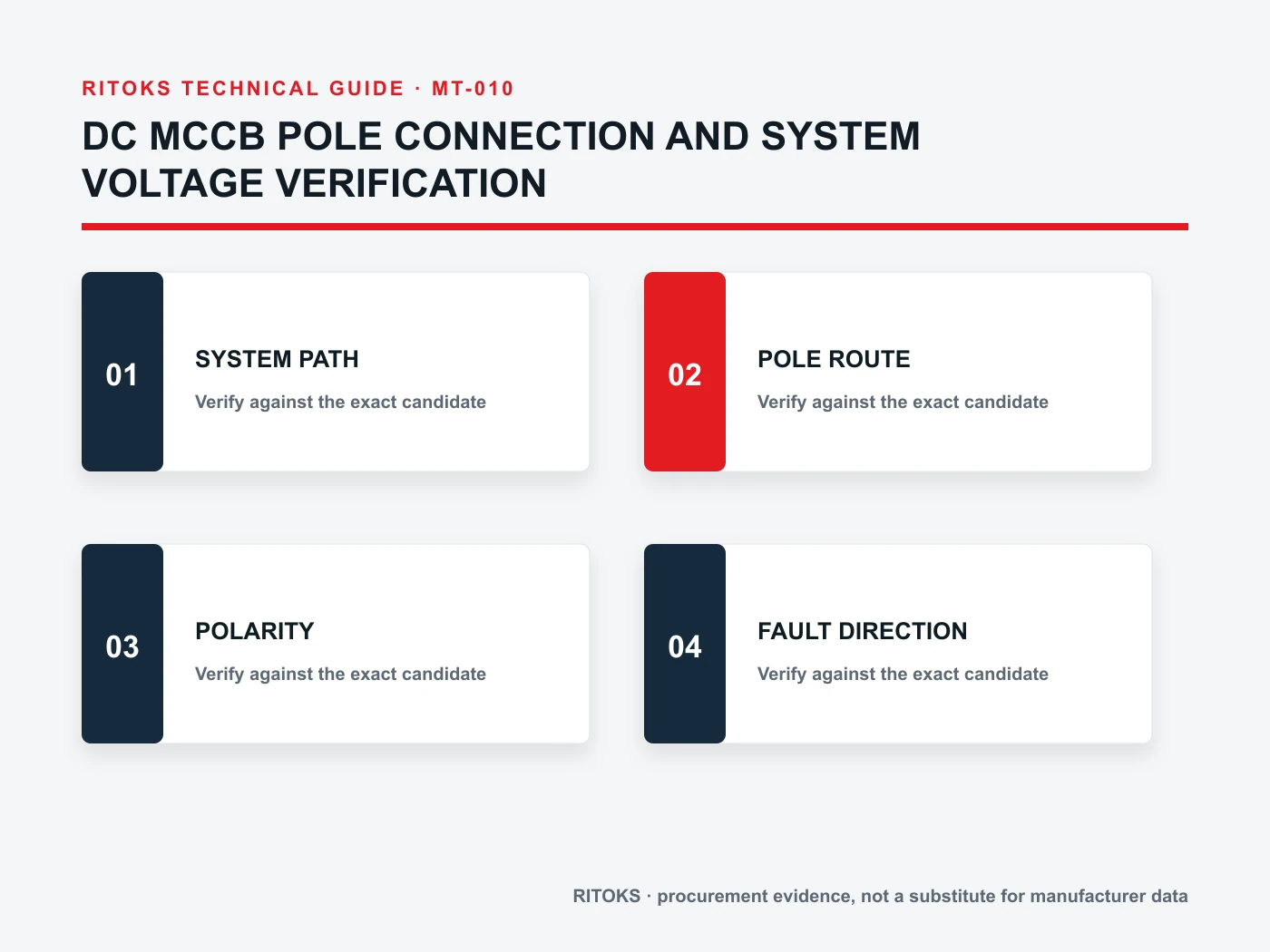
Read the exact diagram, terminal by terminal
Obtain the manufacturer drawing for the exact MCCB model, frame, pole count and accessory arrangement. Identify line and load terminals, polarity marks, approved bridges and which poles are linked. Some connections may be factory-provided, while others require specific approved links. Do not substitute a locally fabricated bridge unless the manufacturer documents and project design allow it.
Compare the diagram with the assembly drawing before procurement and again after installation. A source/load reversal, missing series link or relocation of a grounded conductor can invalidate the assumed rating. Normal operation may not reveal the problem. The critical performance is needed during a fault, when improvisation is too late.
Confirm that the diagram corresponds to the required rated voltage and fault duty. One product family may show multiple diagrams for different distribution systems. The drawing in a sales brochure should not override a newer model-specific installation manual; record the revision used for approval.
Keep series and parallel connections distinct
Series-pole connection and parallel-pole connection address different design questions. Series arrangements can be used in specific products to support a higher DC voltage. Parallel arrangements may be offered in specific designs for current capability. Neither is a general field modification. Applying one scheme's rating to the other creates an unsupported claim.
Ask the supplier whether a proposed arrangement is approved, what accessories are required and how current is shared if parallel poles are involved. Heat, terminal loading and fault interruption remain exact-model questions. The final circuit drawing should show the arrangement rather than merely list “2P MCCB.”
Verify DC breaking data on the same basis
A DC MCCB's continuous-current rating does not tell you its interrupting duty. Compare the location-specific prospective fault current with the manufacturer's DC breaking-capacity data at the actual operating voltage and pole connection. Ask whether the rating is ultimate, service or another defined measure under the applicable standard and what post-fault service assumptions are made.
Do not mix an AC interrupting number, a lower-voltage DC number and a high-voltage wiring diagram into one implied rating. The evidence must be a consistent exact-model set. If a candidate lacks a clearly documented DC breaking value for the intended arrangement, leave the selection open.
IEC 60947-2 covers low-voltage circuit breakers including DC applications, but a general standard reference is not a substitute for the particular product's rating table. The responsible engineer must also verify the site's applicable code and protection design.
Polarity and fault direction still matter
Some DC MCCBs have directional source and load connections. Series poles may have to be oriented to control the arc in the intended current direction. Show every normal and fault-current direction in the system study, especially where storage, generation or converters can feed from either side.
A product described as “DC rated” is not automatically suitable for bidirectional fault interruption. Ask whether the exact model supports the fault directions that the project requires. If a polarity-dependent scheme cannot meet them, request another documented design instead of reversing the drawing in the field.
A document checklist for the buyer
| Question | Project input | Supplier evidence |
|---|---|---|
| System voltage | Maximum credible voltage at MCCB | DC rating for exact connection |
| Fault current | Prospective current at location | DC breaking data at same voltage |
| Current direction | Normal and fault paths | Polarity/source-load rules |
| Earthing | Grounded or isolated topology | Matching application diagram |
| Mechanical | Busbar, cable and panel layout | Terminal, link and mounting guide |
Record the exact order code, drawing revision and unresolved questions. If a supplier returns only a family title, ask for the precise connection and rating documents before releasing the bill of materials. A conditional quotation should be labeled as such.
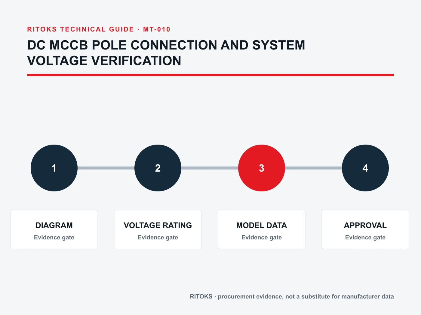
Installation and change control
Before energizing, compare delivered breaker markings, terminal connections and series links with the approved drawing. Check conductor sizes, tightening and enclosure conditions against installation instructions. A correct diagram on paper does not prove that the panel was built that way.
After a breaker substitution, revisit the complete set of assumptions. Pole order, links, terminal orientation and published ratings can differ despite similar frames. Keep the approved manufacturer's drawing in the panel file so maintenance teams can identify the intended path.
If the system grounding or source arrangement changes later, re-evaluate the MCCB connection. A change from one source to two or a converter replacement can alter fault direction and prospective current. The breaker selection is attached to a circuit configuration, not permanently valid for any future topology.
Close the evidence loop before the panel is released
The engineering review should produce more than an approved catalogue number. Keep the final single-line, breaker pole diagram, rating table and fault-current calculation in one controlled record. Identify the person who confirmed that the system voltage and interruption rating refer to the same arrangement. This is especially useful when an OEM repeats the panel design in several voltage variants.
In the shop, label any manufacturer-approved series links and verify their installation during inspection. A temporary test or a visual check of handle operation does not establish fault performance. The assembly must be built to the documented connection and then reviewed under the site's commissioning process. If a link or terminal cannot be inspected after assembly, record its installation before covers are fitted.
When a supplier revises a datasheet or proposes a newer model, compare the relevant rating and diagram pages directly. A retained product-family name is not proof that the connection instructions remained unchanged.
RITOKS inquiry route
The DC MCCB category and two-pole DC MCCB product family identify commercial options, not approval for an unspecified pole connection. Send the system single-line, voltage envelope and fault study via RITOKS contact and ask for exact-model connection and rating documents.
Common questions
Can I multiply a per-pole voltage to get the system rating?
No. Use the complete-device rating stated by the manufacturer for the exact approved pole connection and fault condition.
Does a two-pole breaker always disconnect both polarities?
No. The poles may be arranged in series in a single path. The exact connection drawing shows which conductors actually open.
May I copy a competitor's series-link drawing?
No. Ratings and permitted wiring belong to the specific breaker design and its current manufacturer instructions.
Bottom line
DC MCCB pole connection is a documented system-rating condition. Read the exact diagram against the project single-line, then verify voltage, breaking capacity, polarity and installation requirements on one consistent model basis. A pole count or family headline is not a substitute for that evidence.