
Thermal Overload Relays for Motor Protection · Technical Explainer
Overload Relay Trip Class: Meaning and Exact-Model Verification
Overload Relay Trip Class: Meaning and Exact-Model Verification starts with the system question: What does trip class describe and where must exact curves be checked? A useful selection brief connects the equipment duty, installation and receiving system to a specific orderable product. The article below separates project inputs from product evidence so that a familiar product name does not quietly become a technical approval.
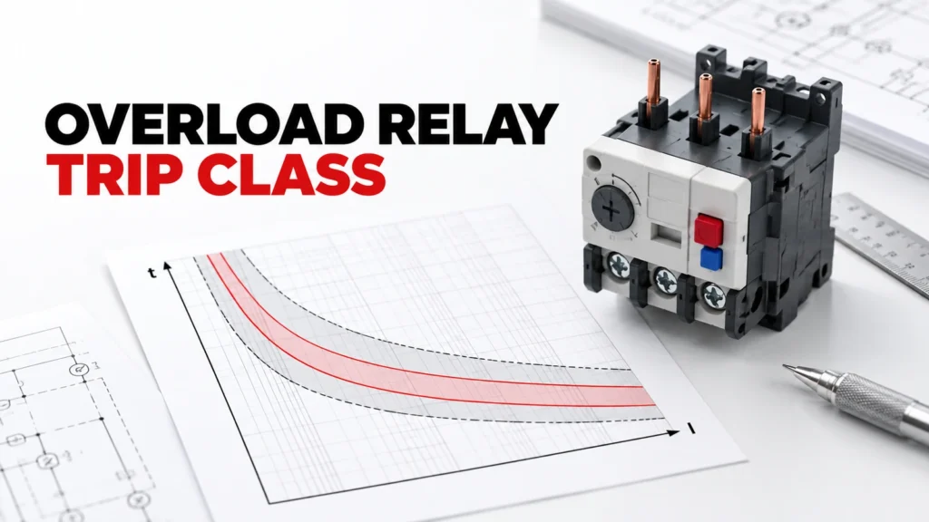
This explainer defines trip class as a characteristic requiring exact-model curves and stated test conditions. It does not assert a specific trip time, setting or coordination result for a RITOKS overload relay.
Decision Inputs at a Glance
| Review area | Project input | Evidence to request |
|---|---|---|
| START TIME | Define actual operating state and system boundary | Approved system drawing or duty record |
| LOCKED ROTOR | Name interface, geometry or control expectation | Exact equipment or product document |
| TRIP CURVE | State environment and installation condition | Site or panel drawing |
| MOTOR LIMIT | Describe service and acceptance requirement | Exact instructions and test plan |
Trip class is about response, not a current rating
An overload relay trip class describes the timing behavior of a relay under defined overload conditions. It helps engineers compare protection response with a motor’s starting behavior and thermal tolerance. It is not simply the relay’s adjustable current range, and it does not prove protection for every motor when the class number appears on a catalog page.
The applicable definition and test point must be read in the exact relay documentation and relevant standard context. A class label without a curve, settings and installation conditions is too thin for a real starter design. Procurement should request those documents with the complete order code.
Begin with the motor duty
Record motor nameplate current, starting method, typical and worst-case start duration, load inertia, frequency of starts and operating environment. The motor supplier may provide permissible thermal limits or starting information. Without these inputs, choosing a faster or slower trip response is a guess.
A high-inertia load may need a different review from an easy-starting load. Yet allowing a start is only one part of the problem; the relay must still protect the motor in credible overload conditions. The engineer must compare both sides of the duty rather than selecting a class because it sounds more tolerant.
Read the exact time-current curve
A time-current curve relates current multiple and trip behavior under specified conditions. Obtain the curve for the quoted relay and its intended setting. Check whether the documented band includes tolerances, initial temperature or other conditions that matter. Do not extract one point and present it as a universal trip time.
Plot or compare the motor start profile and thermal limit using the project’s accepted method. If the curve’s assumptions do not match the application, ask the manufacturer for clarification. Preserve the document revision so a later substitution can be evaluated against the same basis.
Keep current setting separate from trip class
The relay setting range must include the required motor current according to the exact instructions. Trip class describes timing behavior; it does not compensate for an incorrectly selected range or setting. Confirm whether the relay setting is based on the motor nameplate, line current or another value for the actual starter arrangement.
Record the setting in the build documentation and verify it on the finished panel. If the motor, wiring topology or control scheme changes, revisit both the current setting and class review. A neat dial position is not evidence that the selected trip response matches the motor.
Consider hot and repeated starts
Thermal overload devices can respond differently depending on their initial condition and recent operating history. Repeated starts, a short restart interval or a hot motor may change the protection problem. Obtain the exact relay behavior and the motor’s permissible duty; do not invent a universal restart allowance.
The control system may need a defined reset and restart policy. Manual or automatic reset is a separate choice from trip class and should be reviewed for the machine’s safety and operational requirements. An automatic restart path should never be inferred from the relay category.
Check the complete starter combination
The overload relay operates within a starter assembly that may include a contactor, short-circuit protective device and control wiring. Trip class does not establish short-circuit protection or coordination. Ask for applicable exact-device combination data if coordination is required.
Mechanical fit and electrical connection to the contactor also need verification. Similar-looking relays may have different mounting or terminal arrangements. The approval record should name every component in the tested or recommended combination.
Use commissioning to confirm the selected record
Before operation, compare the installed order code, current setting, reset mode, wiring and any control logic with the approved design. Functional checks should follow the project’s authorized procedure and exact instructions. A field test can confirm installation behavior but should not be used to invent a missing manufacturer curve.
Keep the motor data, relay curve, coordination documents and final settings in one file. If an overload event occurs later, that file lets maintenance distinguish a changed load, wrong setting, unsuitable class or other system problem.
Build an Exact-Model Evidence File
For the proposed Thermal Overload Relay, create one approval record with the complete order code, the exact datasheet, the relevant drawing, installation instructions and any curve or test report used for the decision. Date each file or record its revision. A product-family page is useful for discovery, but it does not prove that a particular configuration includes an optional feature or meets a system condition.
Compare every requirement against evidence for the same orderable item. Do not combine a family maximum from one variant with a circuit diagram, accessory list or thermal curve from another. Put unresolved fields in a visible clarification column. If a supplier proposes a substitute, repeat the affected review before approving its technical equivalence.
Keep Project Inputs Separate From Supplier Claims
The project team owns the application record: source and load, operating states, environment, mounting, controls, service and acceptance criteria. The supplier owns the proposed order code and supporting device evidence. Neither side should fill a gap by inference from appearance or a familiar family name. A useful answer can be “data not yet available,” provided that the missing item has an owner and a closure date.
Freeze that record while offers are compared. If the operating duty, cabinet, source, meter, motor or protective architecture changes, issue a revised input sheet and ask each supplier to reconfirm its candidate. This prevents an early quotation from being treated as approval for a later design.
How to Compare Supplier Offers
| Offer item | What to compare | Approval evidence |
|---|---|---|
| Orderable scope | Full code and included accessories | Exact quotation and bill of materials |
| Electrical fit | All applicable operating states | Exact rating, circuit or curve document |
| Mechanical fit | Mounting, terminals and access | Drawing and installation instructions |
| Service plan | Inspection and replacement method | Maintenance instructions |
| Open items | Assumptions, exclusions and exceptions | Written clarification register |
Normalize each Thermal Overload Relay offer to the same application record. A shorter lead time or lower price is meaningful only after the technical scope is comparable. Record whether each supplier included the required accessories, documents and support for commissioning. Keep exceptions explicit, especially when the candidate needs a change to the panel or control design.
Procurement and Commissioning Checkpoints
- Confirm the system boundary, operating states and acceptance criteria.
- Review one complete order code against exact-model documents.
- Resolve electrical, mechanical, environmental and service exceptions.
- Compare delivered scope and document revisions across offers.
- Inspect the received item against the approved record.
- Test the finished assembly under the project’s authorized procedure.
Incoming inspection should check the delivered label, terminals, included accessories and documents against the approved order. A same-family replacement is not automatically acceptable. At commissioning, verify the application-dependent functions that component literature alone cannot establish. The test plan should name representative states and acceptance criteria without inventing universal limits.
RFQ Preparation Checklist
A useful request for quotation on overload relay trip class is concise but complete. Ask for the exact orderable configuration and list unknown values as questions. Do not let the sales description silently answer a technical question that belongs to a calculation, a drawing or a test.
- START TIME
- LOCKED ROTOR
- TRIP CURVE
- MOTOR LIMIT
- ORDER CODE
- SETTING
- CURVE
- COORDINATION
- Applicable document revisions
- Quantity, destination and delivery scope
Request that the supplier state exclusions, assumptions and optional items separately. Keep the technical clarification record with the quotation so procurement and engineering review the same scope. If a critical input is still missing, the candidate may remain commercially interesting, but its technical approval stays open.
Frequently Asked Questions
Can a Thermal Overload Relay be chosen from one headline rating?
No. The application, exact configuration and relevant electrical, mechanical, thermal and environmental conditions must be reviewed together. A catalog title is a starting point for discovery, not a complete approval record.
Does a family page prove an exact connection or accessory?
No. Use the proposed order code and its current drawing, datasheet and installation instructions. Optional features or alternate terminal arrangements may differ within a family.
What if the supplier cannot provide one required value?
Mark the value unresolved, identify who will obtain it and pause the affected decision. Do not convert an assumption into a verified claim simply because a purchase date is approaching.
Where to Continue the Review
Browse the Thermal Overload Relay category for the available product family, then review the related product page as a candidate starting point. These pages identify the commercial destination; the exact model documents decide application suitability. For a project-specific comparison, send the system inputs and open questions through the RITOKS inquiry page.
If another device or method appears more suitable after reviewing the evidence, revise the design brief before asking for a substitution. Keep the record tied to the final circuit and installation, not just to the product family that first attracted attention.