
Solar Fuse Links for PV DC Protection · Technical Explainer
PV String and Array Fuse Protection: Application Context and Verification
PV string and array fuse protection is a system decision, not a fuse size copied from a module label. A designer must know how strings are combined, which sources can feed a fault, what the cold-weather open-circuit voltage can be and which equipment the fuse is intended to protect. A gPV fuse-link category identifies a type of component; it does not by itself decide where fuses are required.
This application guide explains what to verify at string and array positions. It does not prescribe a fuse rating or claim that every PV installation needs the same protection arrangement. Exact module data, inverter instructions, site conditions and applicable electrical rules govern the final design.
Map the PV source architecture
Draw each string, the combiner, array output and downstream inverter or DC equipment. Mark the number of strings in parallel and any alternate paths that can backfeed a faulted string. The need for string overcurrent protection depends on available reverse current and equipment limits, not simply on the fact that the circuit is solar.
Provide module data including short-circuit current, open-circuit voltage and the maximum series fuse rating or other manufacturer limit where specified. Keep the module document revision in the design file. An array with one string behaves differently from a combiner with many strings because other strings may contribute to a fault.
Record how strings enter combiner boxes, whether both polarities require protection under the site design, and the earthing arrangement. Do not copy another project's fuse placement without checking its source topology. A change in the number of parallel strings can change the available reverse current and require review.
Differentiate string and array positions
A string fuse position protects a branch within the parallel network according to the system design. An array-output fuse position is nearer the combined output and may have a different normal current and fault duty. The same fuse-link body format should not be assumed suitable for both locations without matching current, voltage and interruption data.
Use a location-specific schedule: circuit identifier, normal current, maximum voltage, prospective fault current, conductor size, holder and service condition. The schedule makes it clear whether the proposed link belongs to one string, a combined output or auxiliary DC circuit. Supplier pages can then be evaluated against the right position.
IEC 60269-6 addresses fuse-links for protection of PV strings and arrays. Its scope confirms that PV protection has additional requirements, but it does not establish that a particular RITOKS order code has a given rating or certification. Require the exact fuse-link datasheet.

Check maximum DC voltage at the location
PV string open-circuit voltage changes with temperature and configuration. The designer should calculate the maximum relevant system voltage for the site and compare it with the exact fuse-link and holder DC ratings. Nominal module voltage or inverter operating voltage is not enough.
Check that the entire assembly is rated for the system: link, holder, terminals, conductor insulation and enclosure. A fuse link with a high DC voltage rating does not upgrade an inadequately rated holder. Do not mix components based only on cartridge dimensions.
Ask whether the product rating applies to the proposed polarity and installation conditions. Use the manufacturer instructions for the exact link and holder combination. A generic AC fuse of the same size cannot substitute for a PV-rated DC link without appropriate evidence.
Review current and interruption duty separately
Provide the maximum continuous current the fuse carries in the installed enclosure and the prospective fault current it must interrupt. Fuse selection also has to respect the protected module or conductor limits. These constraints may pull in different directions; a larger current rating can avoid nuisance operation while leaving equipment less protected.
PV sources can supply fault currents with different characteristics from a conventional AC source. Ask for gPV application and interruption evidence relevant to the system. A high breaking-capacity headline does not tell you the fuse's behavior near lower fault currents or under the exact DC voltage and thermal conditions.
Document temperature inside the combiner box and any grouping or adjacent-device derating. Continuous current capability may be affected by ambient and holder contact quality. Final design should use link and holder instructions rather than assuming laboratory ratings transfer unchanged to a crowded outdoor enclosure.
Treat fuse-link and holder as an assembly
Match physical size, current range, DC voltage, terminals and thermal requirements for the exact fuse link and holder. A cartridge that fits mechanically may still be an unapproved combination. Ask for manufacturer confirmation of the pairing and any installation or replacement limitations.
Consider how maintenance staff will identify and replace a blown fuse. Label string positions, keep spare order codes in the panel record and provide a safe isolation procedure. A fuse holder is not automatically a load-break disconnect; verify any switching function separately.
Inspect holder contact condition, wiring torque and enclosure sealing during maintenance. Heat damage or corrosion can change contact resistance. Replacing only the fuse link without addressing a damaged holder can leave the assembly unreliable.
A PV fuse application record
| Review item | Project evidence | Supplier evidence |
|---|---|---|
| Position | String or array single-line | Link/holder application scope |
| Voltage | Cold-condition maximum DC | Exact DC ratings |
| Current | Continuous and reverse-fault paths | Current and gPV time-current data |
| Fault | Prospective current at position | Interruption data at system voltage |
| Assembly | Enclosure and conductor layout | Holder compatibility and mounting guide |
Keep each check tied to an exact order code. If the inverter or module supplier specifies a protection condition, compare it with the fuse proposal and preserve the source document. An unresolved condition should remain pending in the design review rather than being converted into a guessed rating.
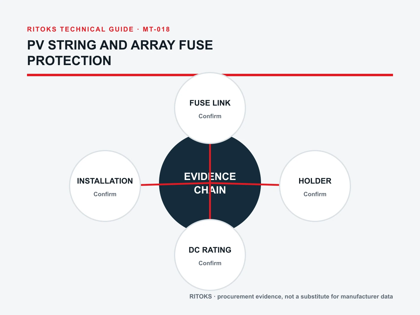
How RITOKS options enter the review
The DC fuse links category is a starting point. The 10×38 gPV link family, 10×65 gPV link family and MGPV solar fuse family represent commercial options, not automatically interchangeable link/holder assemblies.
Send the PV single-line, module data, maximum system voltage, fault and current study, holder plan and environmental conditions through RITOKS contact. Request exact data and compatibility confirmation. The supplier can then address a specific string or array position rather than a generic “solar fuse” request.
Review changes over the project's life
PV protection should be reviewed when an array is expanded, re-stringed or connected to a different inverter input. An added parallel string changes the sources available to backfeed a fault. A replacement module with different current or voltage characteristics can invalidate a calculation even when it fits the same frame. Record the assumptions that led to the original fuse schedule so maintenance teams know which changes trigger redesign.
Ask the installer to label each combiner input and preserve an as-built single-line drawing. The drawing should identify the link order code, holder order code, polarity arrangement and circuit served. If the site has several arrays built in stages, distinguish them by revision; a generic “PV fuse” label on a spare-parts shelf is not sufficient to prevent a same-size but wrong-rating replacement.
After a fuse operates, investigate the cause before inserting a new cartridge. Inspect conductor insulation, connectors, holder contacts and the affected string. A fuse operation may indicate a continuing fault or a damaged holder. Maintenance personnel must use a site-approved isolation and verification procedure because a PV string can remain energized in daylight after the inverter is switched off.
Procurement questions that keep the review precise
When comparing offers, request the link's full time-current information, DC interruption evidence and applicable standard declaration for the exact order code. Ask for the mating holder's installation sheet and any permitted accessories. If a supplier proposes a different body size, request a revised panel-layout and thermal check rather than treating the substitution as a simple price alternative.
Have the engineer mark each proposed substitution against the circuit schedule: position, maximum voltage, normal current, prospective fault, ambient and protected equipment limit. A “higher-rated” fuse is not automatically more appropriate. Higher voltage capability does not answer current protection, and higher current capability can reduce protection of modules or conductors.
For an outdoor combiner, include the enclosure's exposure and service environment in the request. Water ingress, ultraviolet exposure and temperature swings can affect the assembly and maintenance plan even though the fuse link itself is selected electrically. The enclosure and holder evidence should correspond to the mounted installation, not just to a bench-tested component.
Common questions
Does every PV string require a fuse?
No universal answer follows from the word “PV.” The need depends on parallel-source backfeed, module limits and applicable system rules. Review the actual architecture.
Is a gPV link's voltage rating enough to approve the assembly?
No. Check holder, wiring, enclosure and exact link compatibility at the location's maximum DC voltage and current conditions.
Can an AC fuse of the same size replace a PV link?
Do not assume so. PV DC interruption and application evidence must be confirmed for the exact device.
Bottom line
PV string and array fuse decisions start with source topology and backfeed analysis. Then verify voltage, current, interruption and link-holder compatibility for each exact position. A product-family name is useful for sourcing, but the system study decides the protection architecture.
References
- IEC, IEC 60269-6 PV fuse-link supplementary requirements.
- IEC, IEC 62548-1 photovoltaic arrays design requirements (confirm applicable edition and local rules).