
SCR Thyristor Modules · Technical Explainer
SCR Module Voltage Ratings: Repetitive Peak and System Margin
An SCR module voltage rating must be compared with the voltage that the actual circuit can place across each thyristor in its blocking state. The same module can encounter forward blocking, reverse blocking and transient stresses at different points in an operating cycle. A single catalog number cannot describe all of those conditions or replace a system-level calculation.
This guide explains the questions buyers should ask about repetitive peak ratings and design margin for industrial SCR modules. It does not calculate an approved margin, specify a firing circuit, select a snubber or assert a voltage class for any exact RITOKS product. The project engineer and supplier must work from the same circuit, waveform and exact device datasheet.
The Core Rule
Identify the highest repetitive forward and reverse voltages the SCR must block, then identify credible non-repetitive events. Read the exact module's corresponding datasheet symbols and conditions. Compare each stress with the matching limit, allowing a documented margin that reflects source tolerance, circuit behavior and protection design. Do not treat a surge or test value as a continuous repetitive rating.
Why an SCR Is Not Just a Rectifier Diode
A thyristor remains in a blocking state until its operating conditions and gate command cause conduction. In controlled rectifiers, AC power controllers and soft-start arrangements, the voltage across a device depends on the circuit topology and firing sequence. The blocking interval is therefore part of the selection problem. A bridge-diode voltage example cannot be copied without examining the SCR circuit.
Record whether the proposed module contains one thyristor, a dual arrangement or another internal topology. Draw the actual connection and identify each device position. An assembly name such as “SCR module” does not tell the buyer which junction blocks which polarity under all states. The manufacturer diagram for the exact order code is essential.
| Voltage question | Circuit evidence | Device evidence |
|---|---|---|
| Forward blocking | Maximum repetitive state before triggering | Matching forward repetitive peak declaration |
| Reverse blocking | Maximum repetitive reverse state | Matching reverse repetitive peak declaration |
| Non-repetitive event | Switching or fault waveform at the device | Relevant transient or surge condition, if declared |
| Dynamic stress | Rate of voltage rise and commutation case | Applicable dynamic limits and application note |
| Topology | Project connection and firing sequence | Exact internal circuit and terminal diagram |
Read Symbols and Conditions, Not Only Numbers
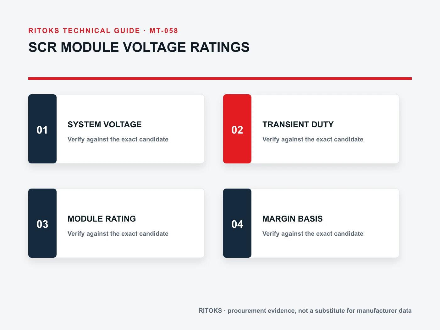
SCR datasheets may list repetitive peak off-state voltage, repetitive peak reverse voltage and non-repetitive peaks as distinct parameters. The symbols, definitions and test conditions matter. Confirm whether a value applies to an individual thyristor in the module, to a specified connection or to a particular device variant. Do not compare unlike parameters because their numerical values happen to look similar.
When a family document shows several voltage classes, mark the row tied to the quoted order code. Ask the supplier to provide the current exact-model document and state any relevant temperature or test condition. A module with the same external outline may have a different voltage class or internal connection.
Define the Source Range and Waveform
Record the source type, phase arrangement, transformer ratio or supply tolerance, frequency, expected waveform and any regeneration or back-feed path. A nominal mains label is not the maximum blocking voltage at every thyristor. The circuit engineer should derive the peak across each device for the intended operating states, including the states before firing and after commutation.
For a controlled rectifier, the DC bus and load can influence device voltage during commutation. For an AC controller, the load's inductive behavior and switching sequence can matter. Avoid broad assumptions based only on load power. Preserve the actual schematic and waveform analysis as the source of the stress figure used in selection.
Consider Startup and Fault States
A selection based only on steady conduction can miss blocking states during startup, shutdown, loss of gate drive, phase loss or a fault response. Identify which of these are credible and how long they persist. The responsible engineer should decide which are repetitive design cases and which are exceptional events. That classification determines which datasheet declaration is relevant.
Do not assign an exceptional event to a repetitive rating without checking the waveform and manufacturer conditions. Conversely, do not rely on a non-repetitive surge value to tolerate an event that happens in normal operation. The supplier should understand the event description rather than receive only a maximum number stripped of its frequency and duration.
Review Voltage Rise and Commutation
Dynamic voltage stress can be important for thyristors. A fast voltage rise across a blocking device and the conditions during commutation may have limits separate from static peak voltage. Ask the engineering team to evaluate these using the exact device's application data. A generous static voltage margin cannot by itself prove that a dynamic condition is acceptable.
Snubbers and suppression networks may be considered when the circuit requires them, but their components and placement depend on topology and measured or calculated behavior. Do not copy an RC network from another SCR arrangement. The RFQ should state whether the supplier is expected to provide application guidance, and which aspects remain with the system designer.
Make Margin a Documented Result
System margin is the relationship between justified circuit stress and the appropriate exact-device limit under its stated conditions. Document source tolerance, uncertain waveform effects, environmental conditions and protective components used in the comparison. There is no universal percentage in this article because an arbitrary number would conceal the assumptions that control the result.
State who owns the calculation and which schematic revision it uses. If the margin is insufficient, the design team may change the device voltage class, circuit, control sequence or protection. Procurement should record the approved outcome and keep any supplier exception visible rather than translating a concern into an unsupported “equivalent” item.
Voltage Is Only One Selection Axis
An SCR with adequate blocking voltage may still fail the current, surge, thermal or gate-drive requirements. Current waveforms and duty determine conduction loss; the module mounting path determines junction temperature; the gate circuit determines triggering under the specified conditions. Keep these reviews separate so a larger voltage label is not mistaken for complete suitability.
The SCR module category and the published MTA dual-SCR, MTC SCR and high-current MTC families are discovery pages. Their titles do not establish any exact variant's blocking limit, gate behavior or system compatibility.
Build an Exact-Model Evidence File
For each proposed order code, retain its datasheet revision, internal connection diagram, forward and reverse repetitive ratings, relevant dynamic limits, current and thermal data, and mounting instructions. Put the project stress cases beside the corresponding manufacturer parameter. If a family chart contains several versions, identify the exact row and reject claims borrowed from a neighboring option.
Include the snubber or protection design record when it is part of the voltage-margin argument. If that design is undecided, mark the module selection provisional. A supplier can confirm available device data, but it cannot validate an unknown transient environment from a catalog page alone.
Questions for an SCR RFQ
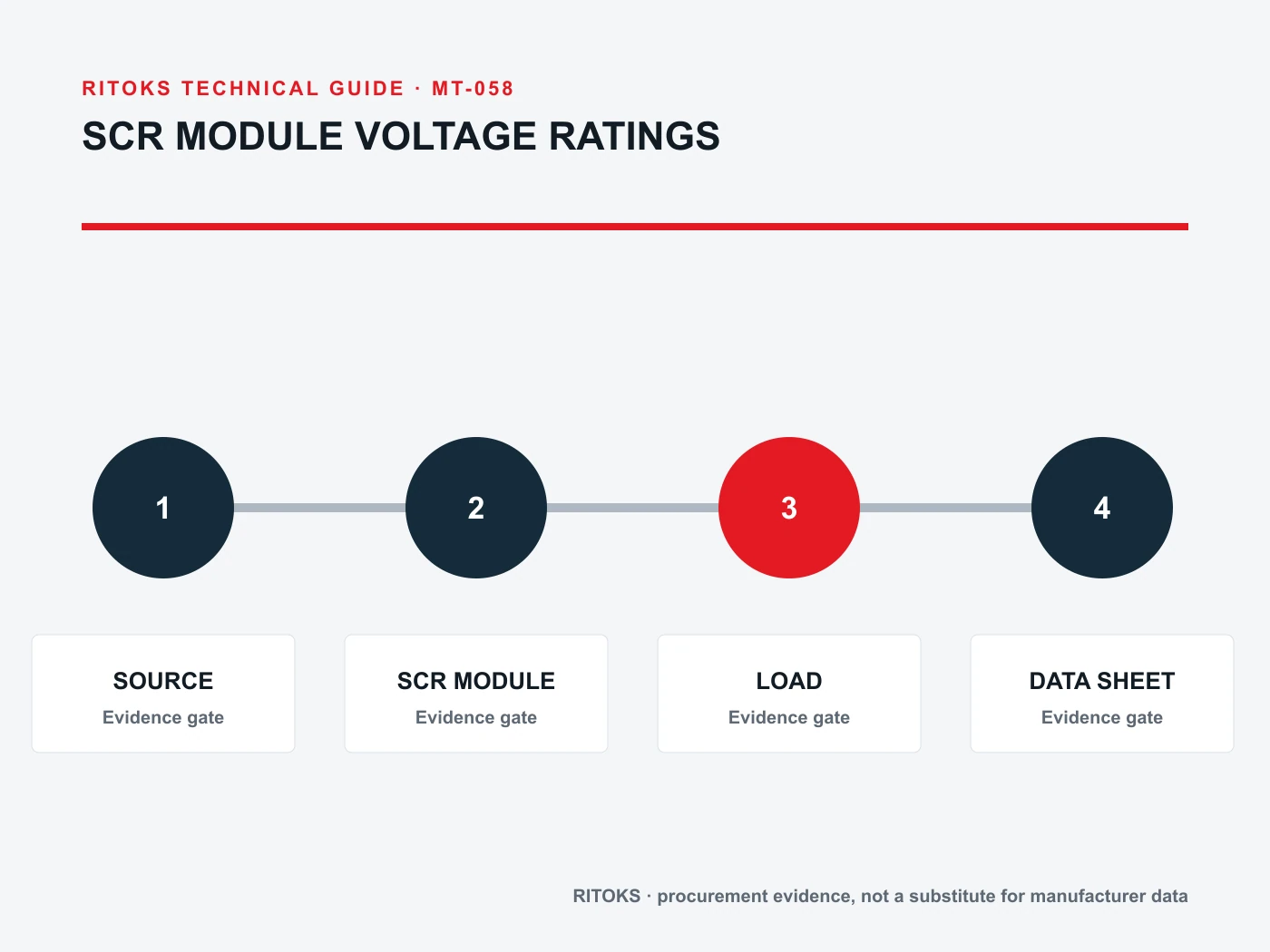
Provide the circuit schematic, source range, topology, switching or firing description, load behavior, maximum repetitive forward and reverse stress estimates, transient cases and thermal environment. Ask for an exact module code, connection diagram and applicable datasheet rows. If engineering assistance is needed, describe the specific open question rather than requesting a generic “recommended SCR.”
Use one comparison sheet for all offers. Record the parameter symbol, value, conditions and document reference for each. Mark differences in internal topology and included accessories before comparing price. If a substitute changes the device structure or voltage class, repeat the affected stress, gate and thermal review.
Common Voltage-Rating Errors
Common errors include comparing nominal AC voltage directly with an SCR blocking rating, using a non-repetitive value for routine operation, ignoring forward versus reverse blocking, and copying a diode-bridge calculation into a controlled circuit. Another is assuming a snubber included in one application note will cover the installation without validating its components and wiring.
Each error can be avoided by preserving three documents: the project waveform or stress calculation, the exact module datasheet and the protective circuit design. The documents must describe the same revision of the system. If they do not, the selection remains open until the responsible engineer resolves the mismatch.
Final Approval Questions
When a supplier returns an alternative voltage class, ask what changed besides the blocking declaration. The same-looking module may have a different current capability, loss profile, gate requirement or availability. Keep the complete order code and its documents attached to the proposal so the engineer can review the substitution as a whole device rather than approve one attractive number in isolation.
- Which exact thyristor arrangement and terminal diagram are proposed?
- What repetitive forward and reverse stresses occur in each governing circuit state?
- Which non-repetitive and dynamic events require separate checks?
- Which exact datasheet symbols and conditions were used for comparison?
- How is voltage margin supported by the source and protection design?
- Have current, gate and thermal suitability been reviewed independently?
Send the circuit context through the RITOKS inquiry page when requesting an exact candidate. Approval should follow the matched circuit and device evidence, not a familiar housing or a single voltage number.