
Power Module Heatsinks · Technical Explainer
SCR and Rectifier Module Heatsink Mounting: Evidence Checklist
SCR and Rectifier Module Heatsink Mounting: Evidence Checklist begins with a controlled application record, not a catalog headline. Buyers should define the real system, installation and service conditions before comparing candidate products. Every decisive claim then needs support from the exact proposed order code.

This evidence checklist organizes the documents needed to review mounting between a power semiconductor module and a heatsink. It does not prescribe a universal torque, flatness, compound thickness, insulation stack or temperature limit; those values must come from the exact module, heatsink, interface and assembly instructions.
Decision Inputs at a Glance
| Review area | Buyer must define | Evidence required |
|---|---|---|
| Geometry | Baseplate, holes, keep-outs and contact area | Exact module and heatsink drawings |
| Interface | Approved material, preparation and application method | Exact installation instruction |
| Fastening | Hardware, sequence, tool and tightening value | Manufacturer mounting procedure |
| Insulation | Required electrical isolation and thermal consequences | Approved insulation-system evidence |
| Thermal verification | Loss, temperatures, airflow and acceptance points | Calculation plus assembled test |
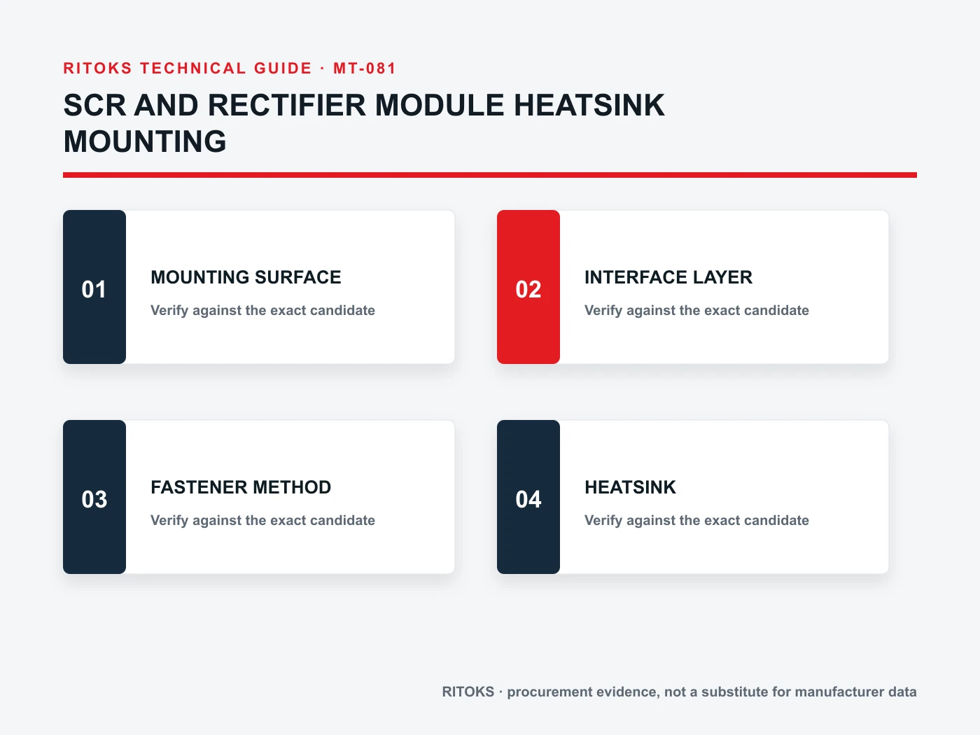
Freeze the Exact Module and Heatsink Pair
Record the full module order code and the exact heatsink extrusion, machining drawing or finished part number. Similar module footprints can differ in hole position, baseplate shape, terminal clearance or mounting instruction. A generic family outline is not enough for machining approval.
Overlay the two controlled drawings and identify the intended contact area, mounting holes, terminal keep-outs, conductor approach and service space. If an adapter plate is proposed, treat it as a separate thermal and mechanical component with its own evidence.
Inspect the Contact Surfaces
The heat-transfer interface depends on the assembled surfaces. Review the exact requirements for flatness, finish, cleanliness and damage limits from the relevant manufacturer documents. Do not substitute a shop rule or a value copied from a neighboring module.
Define how incoming heatsinks and modules are protected from dents, burrs and contamination. Establish an inspection method that can identify a surface problem before fastening hides it.
Specify the Interface Material as a System Component
Thermal compound, pad or isolating material affects contact resistance, assembly process and electrical behavior. Use only a material and application method supported by the complete design. More material is not automatically better, and an improvised layer can prevent proper seating.
Record supplier, grade, thickness or application control, coverage area, storage and replacement rules where applicable. If the interface also provides insulation, confirm its electrical role and how clamping affects its performance.
Follow the Exact Fastening Procedure
Fastener type, washer arrangement, tightening sequence and final torque influence contact pressure and module stress. These details must come from the exact mounting instructions and the approved mechanical design. This article intentionally provides no universal torque number.
Use a controlled tool and document the assembly sequence. If the design requires staged tightening, recheck or settling time, include it in the work instruction. Do not use terminal-torque data as mounting-torque data.
Include Insulation and Clearance in the Review
Determine whether the module base, heatsink or surrounding assembly must be electrically isolated. Add insulators, bushes or barriers only as part of an approved design because they can alter both thermal performance and mechanical stack height.
Check terminal clearance, creepage and service access using the applicable project requirements and exact drawings. The heatsink may be physically large enough but still unsuitable if terminals or busbars cannot be routed safely.
Verify the Finished Thermal Assembly
Calculate semiconductor loss with exact device data and real operating duty. Carry that heat through every interface to the cooling medium. For forced air, include the actual fan, duct, obstruction and inlet condition rather than a free-air assumption.
Test representative assemblies at the specified load and environment. Define measurement locations and acceptance limits before testing. If the module, interface, machining, fan or enclosure changes, assess whether the verification remains applicable.
Build an Exact-Model Evidence File
Create one approval record for the proposed Power Module Heatsink order code. Put each project requirement beside the supplier document that answers it. Preserve the exact datasheet, drawing, curve, table, instruction or selection output used, including its revision or retrieval date. A category page can establish family context, but it cannot prove an exact rating, construction, terminal arrangement or system combination.
Check that every accepted statement describes the same orderable item. Do not combine a family maximum from one variant, a diagram from another and an optional feature from a third. Mark unresolved fields explicitly so they remain visible in technical and commercial review.
Keep Project Inputs Separate From Product Evidence
The project team defines the application: source, load, duty, environment, controls, mounting, service and required functions. The supplier identifies an exact Power Module Heatsink and supports it with exact documents. Neither side should fill a gap by inference from appearance, a shared family name or one matching headline value.
Freeze the application record while quotations are being compared. If the electrical duty, environment, cooling method, enclosure, installation or required function changes, issue a revised record and ask every supplier to reconfirm the candidate.
Define the Acceptance Record Before Ordering
Write the acceptance record before a preferred Power Module Heatsink is chosen. Include the project inputs, proposed order code, included accessories, document revisions, exceptions, assumptions and the person responsible for resolving each open point. This prevents the technical basis from being reconstructed after price negotiations have already narrowed the choice.
Separate mandatory requirements from preferences and future options. A mandatory condition needs direct evidence or a documented engineering decision. A preference can influence comparison but should not be presented as a safety or compliance requirement. Future options should be checked only when the project genuinely expects them, because optional features can change the order code, terminals, dimensions or supporting documents.
Verify the Delivered Item and the Finished Assembly
Incoming inspection should compare the delivered Power Module Heatsink, labels, accessories and documents with the approved record. Do not accept a same-family replacement solely because its appearance or one rating matches. Record any substitution and repeat the affected review before installation.
After assembly, verify the functions and conditions that cannot be proven from component literature alone. The check may include mechanical fit, wiring against the approved diagram, control behavior, temperatures, airflow, alarms or service access as applicable. Define representative operating states and acceptance criteria in the project test plan rather than inventing universal limits in the purchase order.
Common Procurement Errors
- Selecting a Power Module Heatsink from one headline value while the application context remains incomplete.
- Using a curve, circuit, drawing or claim from a neighboring order code.
- Treating a category page, product photograph or nominal size as exact compatibility evidence.
- Assuming an accessory, system function or coordination result is included without documentation.
- Approving a substitute without repeating the electrical, mechanical and evidence review.
Resolve these gaps before comparing price and lead time. A proposal may remain commercially interesting while technically incomplete, but missing evidence must not disappear inside the quotation.
How to Compare Supplier Offers
| Review area | Buyer must define | Evidence required |
|---|---|---|
| Order code | Complete proposed item and included accessories | Exact datasheet and scope |
| Application match | Submitted operating and environmental conditions | Written response to each requirement |
| Mechanical integration | Mounting, terminals, clearances and service | Exact drawings and instructions |
| Electrical evidence | Applicable ratings, curves and topology | Exact-model technical documents |
| Open points | Unknowns, exceptions and assumptions | Dated clarification list |
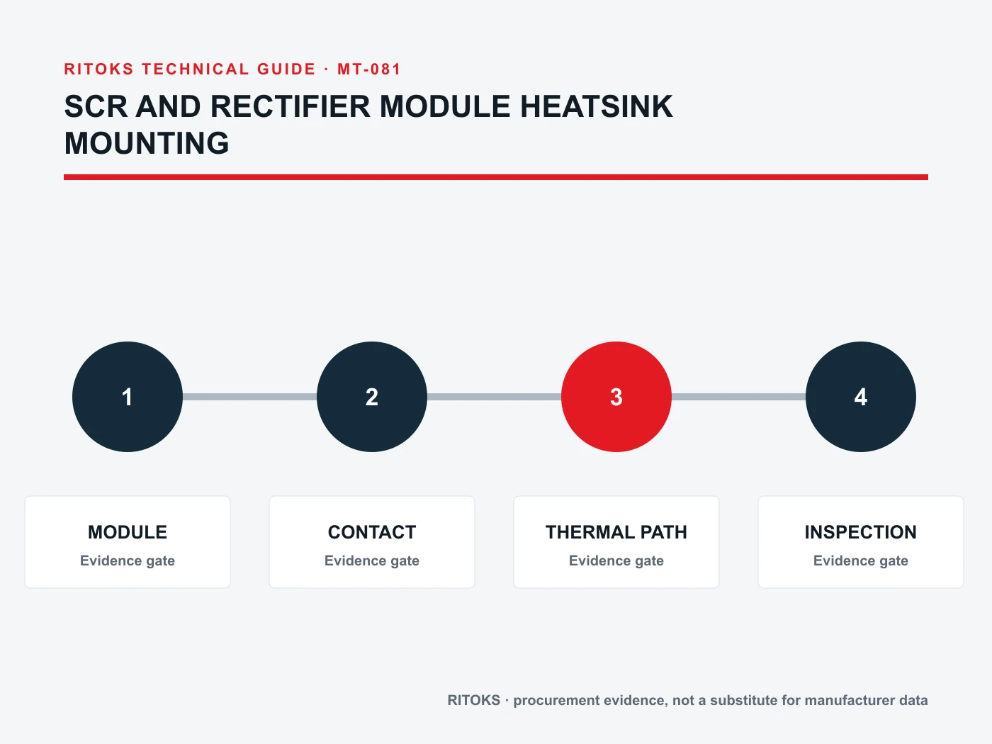
Normalize every Power Module Heatsink offer to the same application record. Keep document revisions, test conditions, included accessories and open questions beside each value. This makes differences in delivered scope visible and prevents a lower-cost but narrower offer from appearing equivalent to a complete proposal.
Decision Workflow
- Freeze the system boundary and operating states.
- Record electrical, mechanical, environmental and service inputs.
- Choose a complete candidate order code for review.
- Verify every critical statement against exact-model evidence.
- Resolve exceptions and assumptions before commercial comparison.
- Validate the finished assembly where application risk requires it.
Stop when a critical input is unknown, the quoted model is ambiguous, a required claim is supported only by another manufacturer or order code, or the installation falls outside available evidence. These are engineering gaps, not editorial details.
RFQ Preparation Checklist
A useful RFQ for scr module heatsink mounting is concise enough to answer and complete enough to prevent silent assumptions. Identify unknown values as questions and require a full orderable code rather than a generic family recommendation.
- EXACT DRAWINGS
- SURFACE CONDITION
- INTERFACE MATERIAL
- FASTENING METHOD
- DEVICE LOSS
- CONTACT PATH
- HEATSINK
- AIRFLOW TEST
- Required documents and revisions
- Quantity, destination and requested delivery scope
Ask the supplier to state exclusions, assumptions and options separately. Record quantity and destination after the technical inputs so commercial terms do not obscure unresolved engineering questions.
Frequently Asked Questions
Can I select a Power Module Heatsink from one rating or size?
No. Selection requires the complete application, exact construction and all applicable electrical, mechanical, thermal, environmental and documentation conditions.
Can I use a family page as approval evidence?
A family page is useful for orientation. Approval should use the exact order-code datasheet, drawing, instructions and project-specific engineering evidence.
Are similar-looking models interchangeable?
Not automatically. Similar housings can contain different circuits, materials, terminals, ratings or accessories. Repeat the review for every substitute.
What should remain open in the quotation?
Any missing project input, unverified exact-model claim, unclear included accessory or unresolved installation condition should be listed as an open point rather than assumed.
Related RITOKS Resources and RFQ
Browse the Power Module Heatsink product category, review the primary related product page, review related product option 2. These pages provide commercial context; exact suitability still depends on the project record and the quoted order code.
When the technical record is ready, send the application and evidence requirements to RITOKS for a documented quotation. Keep the final selection subject to the project engineer’s approval and the current manufacturer documentation.