
AC Contactors for Industrial Motor Control · RFQ Checklist
AC Contactor RFQ Checklist: Load, Coil, Poles and Accessories
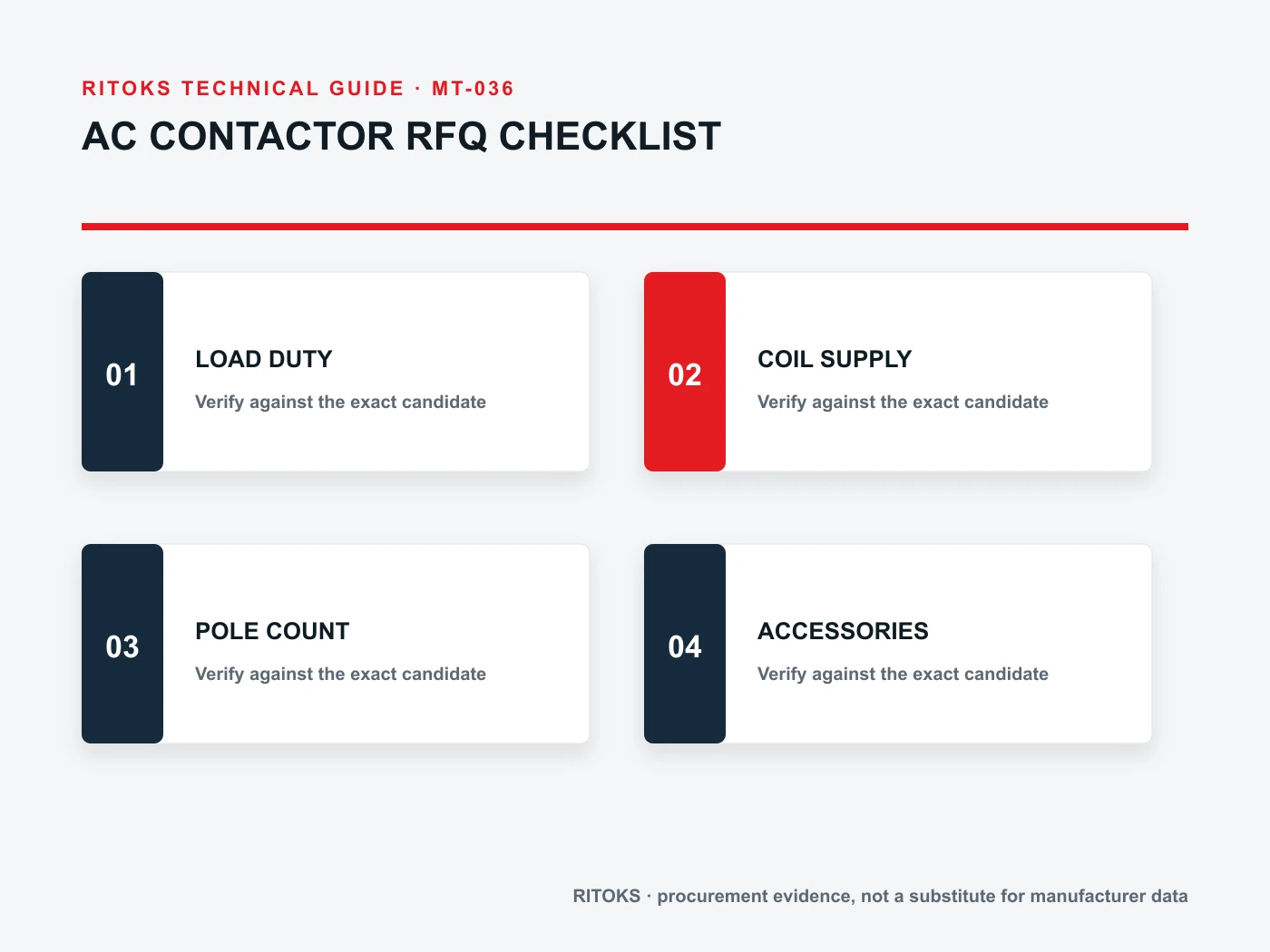
An AC contactor RFQ should identify the load, coil supply, main poles and auxiliary functions separately. A current rating alone cannot tell a supplier whether the device will switch a motor, heater or another load, and a physically similar contactor may have the wrong coil or auxiliary-contact arrangement.

This buyer checklist turns those distinctions into a comparable inquiry. It does not select a particular model or claim that an arbitrary contactor and overload relay have been tested together. Exact order-code documentation and the panel design remain the approval basis.
Describe the load before the contactor
State whether the load is a motor, resistive heater, lighting circuit, transformer or another device. Provide its supply voltage, frequency, normal current, making current, expected switching current and operating cycle where known. The relevant utilization category and duty are more meaningful than an ampere label detached from the application.
For a motor, send nameplate data, starting method, starting current and frequency of starts. For a heater, explain whether control is occasional or rapid cycling. For unusual loads, include a waveform or manufacturer data. Schneider Electric's contactor specification guidance explicitly separates main contacts, auxiliary contacts and coil, and asks for load duty when a utilization category has not been fixed.
Ask the supplier to state the exact candidate's rated operational current and voltage at the applicable utilization category. Do not compare one model's resistive-load rating with another model's motor-duty rating as though they were equivalent. Keep the test condition beside the figure in the comparison sheet.
Specify main poles and circuit arrangement
Provide a single-line showing how many poles must switch, whether the contacts are normally open or normally closed, and whether neutral or another conductor is involved. Some applications require interlocked pairs or reversing arrangements rather than one contactor. The number of visible terminals on a product photo is not a substitute for an exact connection diagram.
Clarify whether the contactor is the sole switching element or part of a motor starter. Its relationship with overload and short-circuit protection should be shown, including upstream protective device order codes where known. A contactor does not become a fault-interrupting breaker because it is installed in a protected panel.
For reversing or changeover duty, describe mechanical and electrical interlocks, control logic and required contact arrangement. A supplier must know whether an accessory is factory fitted, separately ordered or built into a starter assembly. Do not assume an auxiliary contact can serve as a power pole.
Match the coil to the real control supply
State the control voltage, AC or DC type, frequency for AC coils, allowable supply variation and source capacity. The coil rating is a separate selection from the main-contact rating. A contactor with appropriate power poles may fail to pick up or drop out correctly if the coil supply is wrong.
Ask about coil inrush and holding consumption where the PLC output, control transformer or power supply capacity is limited. If an interface relay or suppression component is required, include it in the panel design. Coil suppression can affect release behavior, so choose it from manufacturer guidance rather than adding an arbitrary component later.
Explain the desired response to control-power loss and restoration. A machine that may restart automatically needs a deliberate control scheme. A contactor's coil does not independently decide the safety of automatic restart; the project logic and risk assessment do.
Count auxiliary contacts by function
List each normally open and normally closed auxiliary contact required for seal-in, feedback, interlocking, indication or remote monitoring. State the circuit voltage and load on each contact. Auxiliary contacts may be built in or added by compatible blocks; the exact order code and permissible mounting positions need confirmation.
Do not equate an ordinary auxiliary contact with a safety-rated mirror contact without exact evidence. If the control architecture depends on a particular contact behavior, name the requirement and ask for the relevant manufacturer documentation. Similar-looking blocks can have different functions.
Prepare a control schematic rather than a count alone. “Two NO contacts” is ambiguous if one must be available before an interlock or if mounting location matters. The supplier can check accessory compatibility only when the intended function is visible.
Provide installation and coordination conditions
Include ambient temperature, panel-space limits, mounting orientation, conductor sizes, terminal style and nearby heat sources. Ask for the exact device dimensions, clearance and installation instructions. A substitute with a larger frame may affect enclosure ventilation, cable bend or DIN-rail capacity.
Identify the upstream fuse or breaker, any overload relay and the prospective fault current. If the project requires starter coordination or a panel short-circuit rating, ask for tested combination evidence for the actual devices. A contactor current rating alone cannot establish the assembly's fault performance.
IEC 60947-4-1 covers electromechanical contactors and motor starters, but citing a standard does not prove that a particular RITOKS combination is approved. Keep the exact-model datasheet and applicable coordination documents in the project file.
Use a supplier-response matrix
| RFQ field | Project supplies | Supplier returns |
|---|---|---|
| Load | Type, current, voltage and duty | Rating at matching utilization category |
| Power contacts | Poles and circuit diagram | Exact contact arrangement |
| Coil | Control supply and logic | Coil code and consumption |
| Auxiliaries | Contact functions and signals | Compatible block order codes |
| Panel | Space, ambient and wiring | Drawing and installation rules |
| Protection | Upstream and overload devices | Coordination evidence if required |
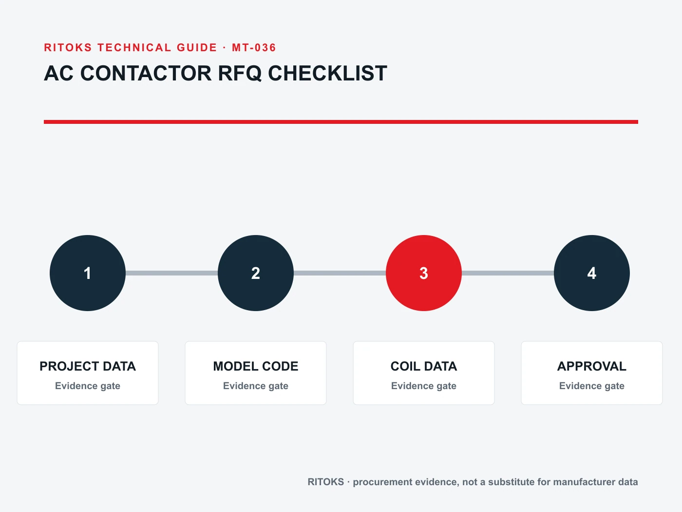
Require the full order code, including coil suffix and accessories. Compare candidates at the same duty. If the supplier proposes an alternative that changes the coil, terminal orientation or auxiliary arrangement, record the necessary wiring or control-logic revision.
Clarify replacement versus new-design requests
For a replacement, send the old order code, photos of labels, original panel schematic and reason for replacement. State which interfaces cannot change. Do not assume a new device is drop-in because its frame width or current label is similar. Verify coil voltage, contact arrangement, mounting, terminals and auxiliary blocks.
For a new design, name performance and space requirements without locking the supplier into an arbitrary old part number. Ask for a proposed device and clearly list unresolved inputs. A quotation can be conditional while engineering finalizes the load waveform or protection scheme, but it should not be mistaken for final approval.
Plan commissioning checks for coil pickup, commanded stop, auxiliary feedback and overload-trip response in the complete assembly. These tests verify wiring and control behavior; they do not replace type-test evidence for fault duty. Keep settings and drawings with the as-built panel.
RITOKS category and quotation route
The AC contactor category and ZS3TF contactor family identify the commercial range. Their family description does not establish the exact variant's motor-duty rating, coil or accessory fit.
Send the completed load and control schedule through RITOKS contact. Ask for the exact datasheet, wiring diagram, dimensions and accessory codes. A clear RFQ lets the supplier answer a real application question rather than select from a generic ampere headline.
Resolve accessory and control details before ordering
Accessory lists are often treated as optional afterthoughts, but they can determine whether the machine control sequence works. Separate an auxiliary contact used for a safety-related interlock from one used only for an indicator lamp. State the required normally-open or normally-closed state, the switching duty of the control circuit and whether the contact must be mechanically linked or mirror-rated under the relevant design. Do not infer a safety function from an ordinary auxiliary-contact label.
Review any surge-suppression module as part of the coil circuit. Suppression can protect a PLC output or reduce electrical noise, but it can also affect release timing. The exact module must fit the coil technology and the control sequence. If the panel uses an electronic output, ask for inrush and holding consumption so the output's capability can be checked against the exact device.
Confirm whether a mechanical interlock, overload relay, auxiliary block or terminal cover is required and whether it mounts on the chosen frame. A catalog photograph may show accessories that are not included in the base contactor. Require separate order codes and an assembled dimensional drawing when space is tight.
Review substitution by function, not headline current
If a quoted model is unavailable, ask the supplier to mark every deviation in the RFQ matrix. A replacement with more thermal current may still differ in utilization-category rating, coil behavior, terminal position or auxiliary-contact arrangement. The buyer should not approve it until the electrical designer checks the circuit and panel fit.
Keep the decision trail with the machine documentation: original requirement, supplier response, accepted deviations and commissioning result. This makes later spare-parts sourcing less dependent on a single person remembering why a contactor was chosen. For repeat machines, review the first built panel before releasing the same order code across the whole production batch.
When asking for coordination information, provide the actual upstream protective device and the overload arrangement. Fault-withstand or coordination claims are assembly- and test-condition-specific. A statement about a contactor family alone is not enough to approve a different breaker, fuse or wiring configuration. Preserve the supporting table or report for the exact combination and voltage.
Common questions
Is a 24 V control system enough to specify the coil?
No. State AC or DC, supply variation, source capacity and switching logic. The exact coil code must match those conditions.
Can a heater-rated contactor be used for a motor with the same current?
Not without checking the motor utilization category and making/breaking duty on the exact model. Load types impose different contact stresses.
Are auxiliary contacts interchangeable?
Only if the manufacturer confirms their compatible series, mounting and contact behavior for the requested function.
Bottom line
An AC contactor RFQ should specify load duty, main poles, coil supply and auxiliary functions as independent fields. Add panel and coordination constraints, then require exact-order-code evidence. That prevents a superficially matching contactor from becoming a costly control-panel substitution.