
DC Miniature Circuit Breakers (MCB) · Technical Explainer
DC MCBs in Battery Circuits: Selection Inputs and Evidence Boundaries
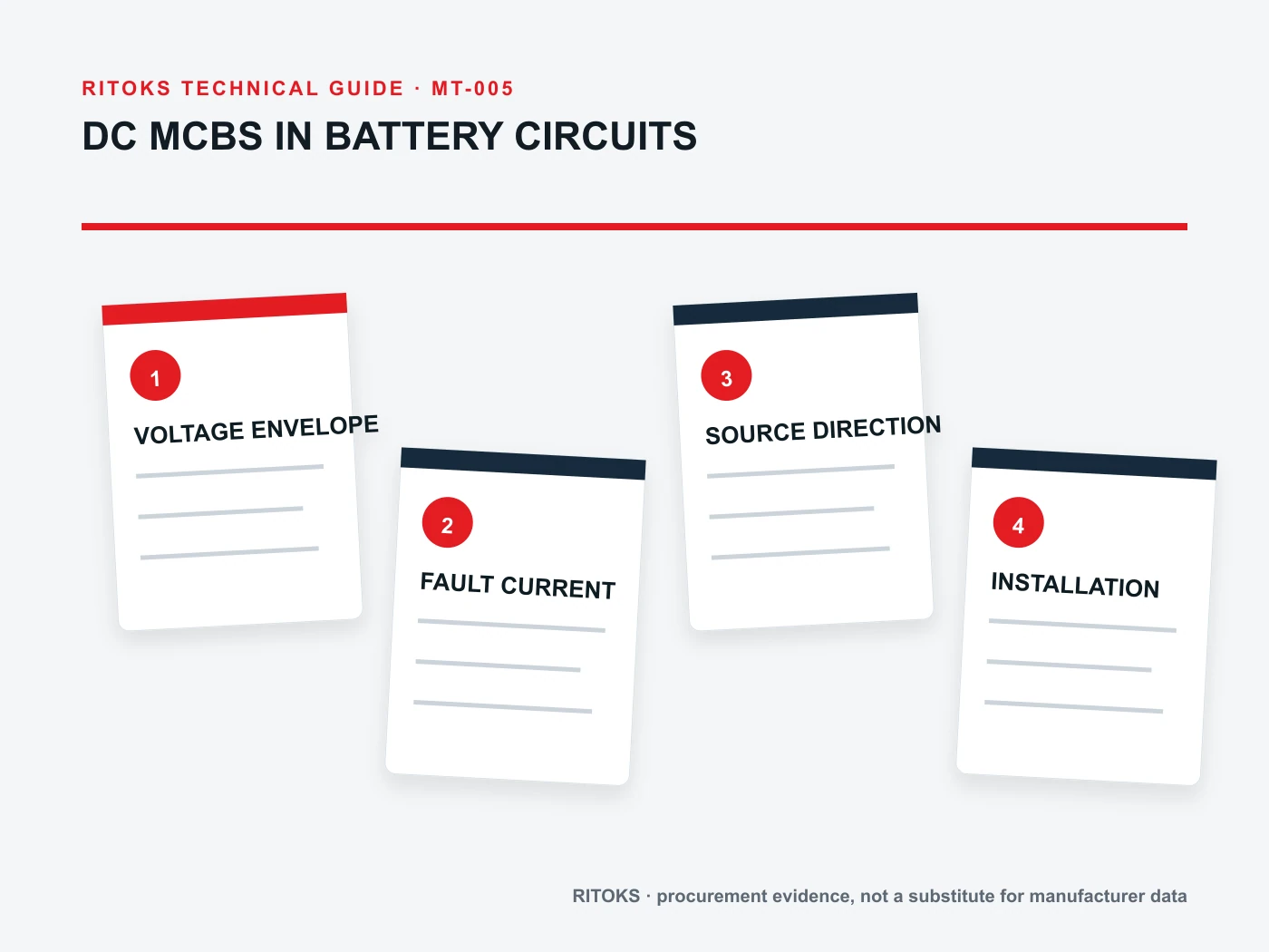
A DC miniature circuit breaker in a battery circuit cannot be selected from a current rating alone. The designer needs the actual battery voltage envelope, fault-current study, source direction, conductor arrangement and intended protection function. A label such as “battery suitable” does not establish that a specific pole configuration can interrupt the fault at this location.
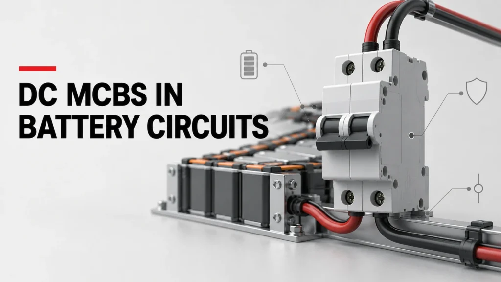
This guide is an input and evidence checklist for engineers and buyers. It does not provide a protective-device setting or substitute for the system protection study. Keep the single-line diagram and the exact candidate datasheet side by side throughout the review.
Define the battery circuit before naming the breaker
State whether the proposed device sits at a battery string, combined battery output, DC distribution branch, converter connection or auxiliary circuit. Those locations can have different normal currents and different sources of prospective fault current. A branch with a battery on one side and power electronics on the other should not be reduced to a generic source-and-load sketch.
Record the operating states: charging, discharging, maintenance isolation, parallel strings and any bypass or alternate feed. Mark each state on the drawing. The exercise helps reveal whether current can flow in both directions and whether a breaker marked for a particular source terminal can be installed as proposed. Do not assume that charge current and short-circuit current follow the same path.
Describe the purpose of the device precisely. Overcurrent protection, switching, isolation and emergency disconnection are not interchangeable claims. If more than one function is required, the project specification should state each function and the evidence expected for it. The DC miniature circuit breaker category identifies a commercial family; it does not decide a protection scheme.
Collect the voltage envelope, not only nominal voltage
Battery terminal voltage changes with state of charge, operating mode and temperature. The system engineer should provide the maximum and minimum voltages relevant to this breaker position and identify transient or charging conditions the device is expected to withstand. The candidate’s DC rating must be checked against the maximum relevant circuit voltage using its exact pole and wiring configuration.
A catalogue headline may list several voltages for different numbers of poles or connection arrangements. Do not carry the highest figure across to a different wiring arrangement. Ask for the manufacturer's diagram showing the proposed series-pole connection, if applicable, and match that diagram to the panel drawing. An AC voltage rating is not evidence of DC interruption performance.
Also document the battery system’s earthing and conductor scheme. A designer must know which conductors are protected and disconnected, what remains energized after operation and whether a ground-fault scenario changes the current path. These are system questions, not details that a breaker supplier can infer from a nominal voltage number.
Establish prospective fault current at the actual location
Provide the prospective short-circuit current at the breaker terminals for the relevant operating states. The study should account for the battery assembly, interconnection, parallel paths, converters and other sources that can contribute under a fault. Do not substitute a cell data-sheet number, a charger rating or a generic battery capacity for a location-specific fault result.
Compare the calculated duty with the exact model’s published DC breaking data at the relevant voltage and pole arrangement. Clarify what the manufacturer means by its breaking-capacity notation and the associated test or application conditions. A candidate with adequate continuous current may still be unsuitable if its documented interruption duty does not cover the available fault current.
If the study is incomplete, mark the breaker choice provisional rather than backfilling a plausible fault value. This is especially important where battery strings are paralleled or the converter can contribute to a fault. Procurement can request a candidate range, but approval belongs after the electrical study and manufacturer's evidence agree.
Separate operating current from protective coordination
List continuous current, expected charge and discharge peaks, startup behavior and the duration of any normal transient. Then identify the conductors and equipment the breaker is intended to protect. The nominal breaker current must be evaluated with the manufacturer's derating and ambient assumptions; it should not be chosen simply as the next catalogue value above a single load figure.
The protection engineer should review time-current behavior against the conductors, upstream and downstream protective devices, battery management functions and converter controls. A breaker’s magnetic and thermal behavior cannot be inferred from its case width. Nor does the existence of a battery management system remove the need to verify the physical interrupting function assigned to the breaker.
Ask which operating states must remain coordinated and which fault cases must cause a particular device to open. If selective operation matters, request the relevant manufacturer curves and study results. Avoid promising selectivity from two current ratings without compatible time-current evidence.
Check polarity, source direction and terminal rules
DC interruption can depend on the internal arc-control design and the way poles are connected. Read the exact device’s line/load, polarity and series-pole instructions. A bidirectional normal operating current does not prove that a direction-sensitive breaker will interrupt faults from both sides at every stated voltage. Conversely, a “non-polarized” description still requires exact-model confirmation of its scope.
Place the manufacturer's terminal drawing next to the system single-line. Mark all sources that may feed a fault, including connected power electronics if applicable. If any possible fault direction conflicts with a permitted connection, stop the selection and request an alternative or formal engineering review. Field-reversing an unverified connection is not an acceptable shortcut.
For a deeper comparison of terminal direction claims, use the approved polarity guidance before writing the bill of materials. The product pages for a two-pole DC MCB family and a higher-current DC MCB family are useful starting points for an inquiry, not proof that either family fits this circuit.
Review enclosure and installation conditions
Record ambient temperature, expected enclosure temperature, mounting orientation, ventilation, altitude where relevant, and available panel space. Obtain the candidate’s installation instructions for conductor size, terminals, tightening procedure, spacing and any adjacent-device derating. Thermal performance depends on the actual assembly; a catalogue current rating alone does not cover every enclosure arrangement.
Check whether the device will be operated manually, remotely or only as an automatic protective component. If a lockable isolation point is required, confirm whether the candidate is approved for that function in the proposed configuration. Do not represent a small breaker as a complete battery disconnect merely because its handle has an OFF position.
Build an evidence-based comparison table
| Decision field | Project input | Exact-model evidence |
|---|---|---|
| DC voltage | Maximum relevant circuit voltage | Rating at proposed poles and wiring |
| Fault duty | Prospective current at installation point | DC interruption data and conditions |
| Current | Continuous and transient operating profile | Rating and derating instructions |
| Direction | Charge, discharge and fault-flow paths | Polarity and terminal instructions |
| Installation | Enclosure and conductor arrangement | Mounting and terminal documentation |
Keep the comparison at the exact order-code level. If a supplier sends a family catalogue rather than a model-specific sheet, list the unresolved fields. A documented “unknown” is more useful than a guessed PASS because it tells engineering and procurement what to request next.
What to send in an RFQ
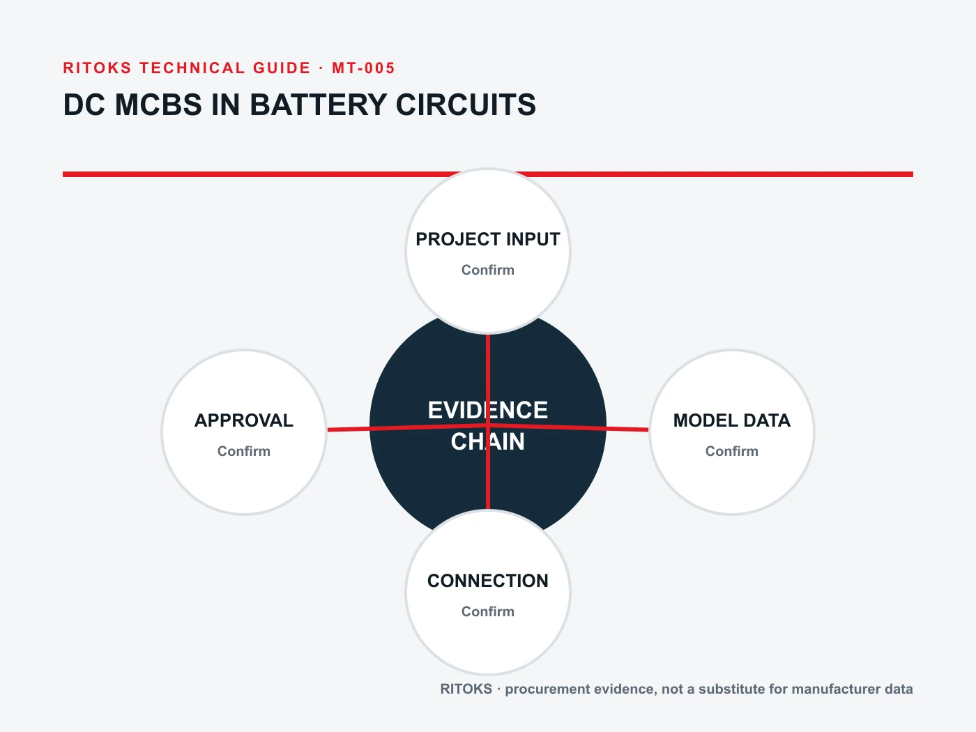
Send the application location, system single-line, battery voltage range, continuous current and transient profile, prospective fault current, expected current directions, earthing scheme, pole and conductor requirements, enclosure conditions, and the desired protective or isolation function. Add the requested documents: exact datasheet, DC breaking data, connection diagram, installation instructions and order-code confirmation.
State which inputs are validated and which are still provisional. That distinction prevents a quotation from being mistaken for a completed engineering approval. If the supplier proposes an alternative model or pole count, ask for a revised comparison against the same project inputs. A product substitute should not inherit the original device’s approval without review.
Use the RITOKS inquiry route to share the documented requirement, while retaining responsibility for the project protection study and final design approval. A clear RFQ allows the supplier to answer specific compatibility questions instead of guessing from a broad phrase such as “breaker for battery.”
Questions engineers should close before release
Can a DC MCB be chosen from battery capacity?
No. Capacity does not describe the maximum circuit voltage, the fault current at the breaker, the operating current profile or the connection rules. Supply those project-specific inputs before checking candidate documentation.
Does bidirectional charging require a non-polarized breaker?
It requires a review of current and fault direction at the specific device position. The appropriate breaker and wiring depend on documented behavior in every relevant state. Do not treat a broad polarity label as a complete answer.
Is a quoted device approved once the rating matches?
No. Verify interruption duty, voltage at the proposed poles, terminal orientation, installation conditions and coordination. Approval should reference the exact model and drawing revision reviewed by the engineer.
Bottom line
Start with the battery circuit and its fault study; then compare exact-model documents. The strongest inquiry names both the intended protective function and the conditions under which the proposed DC MCB must perform. Leave unresolved values open for engineering review rather than turning a product-family page into a safety claim.
References
- IEC, IEC 60947-2 circuit-breaker publication (consult the current edition and exact product documentation).
- U.S. Department of Energy, Energy Storage Safety Strategic Plan (system-level battery safety context).