
Diode Rectifier Modules · Technical Explainer
Diode Module Forward Voltage and Power-Loss Evidence
Forward voltage is one of the inputs used to estimate heat in a power diode module. It is not a fixed penalty that can be copied from one current, temperature or topology to another. Before comparing modules, the engineer needs the actual current waveform, conducting path, device temperature and the exact-model forward-characteristic data.
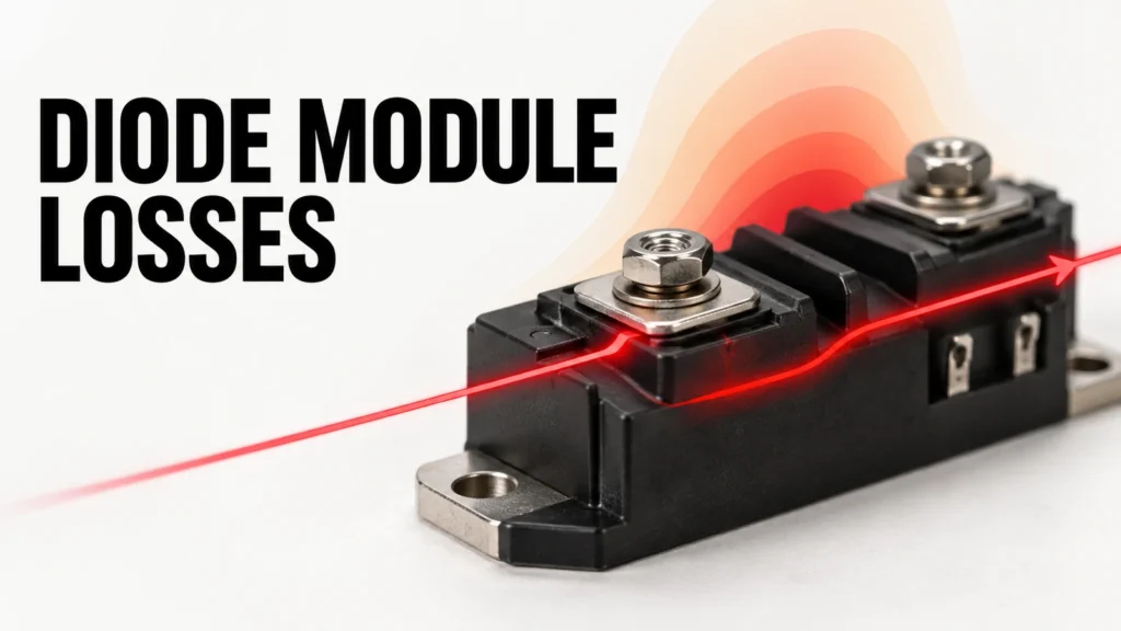
This article explains what diode forward-voltage information can and cannot establish for a thermal review. It does not prescribe a loss number for a RITOKS module or replace a system calculation. The supplier's current datasheet and the application's duty profile remain decisive.
What forward voltage represents
A diode conducts in its forward direction with a voltage drop across it. Multiplying an appropriate instantaneous voltage by the instantaneous current gives instantaneous electrical loss, which appears mainly as heat in the device. The total heat over a cycle depends on how current and voltage vary together, not only on a single point read from a graph.
Power-module datasheets may show forward-voltage curves at multiple junction temperatures or provide a simplified threshold-plus-slope model. Those presentations answer different calculation needs. A typical curve helps understand behavior, but a design margin may require a maximum characteristic or manufacturer-recommended method. Confirm which representation the supplier expects for worst-case thermal work.
Temperature matters because diode forward behavior changes as the semiconductor warms. Do not mix a room-temperature curve with a hot operating current and treat the result as a validated maximum loss. Infineon's semiconductor application material discusses the temperature dependence of diode forward drop; the magnitude and direction over a particular operating range must be taken from the exact device data.
Use the current waveform, not only the nameplate current
Ask how the diode conducts in the actual circuit. A rectifier leg, freewheel path and anti-reverse path can have very different conduction intervals even if the load current is similar. Capture average, RMS, peak and duty-cycle information as required by the manufacturer's calculation model. A smooth DC current and a narrow repetitive pulse should not be treated as equivalent merely because their average values match.
Record the circuit topology and which chips or internal diode paths carry current. In a module containing more than one device, total module heat is the sum of relevant element losses, while the hottest element may control the junction-temperature limit. A connection diagram is therefore part of the thermal analysis, not just a wiring accessory.
Include abnormal but credible conditions such as startup, overload, reverse recovery-related events and repeated cycling where they affect the device. Keep continuous thermal duty distinct from short surge survival. A non-repetitive surge rating is not a forward-loss rating for normal operation.
Read the datasheet conditions beside the curve
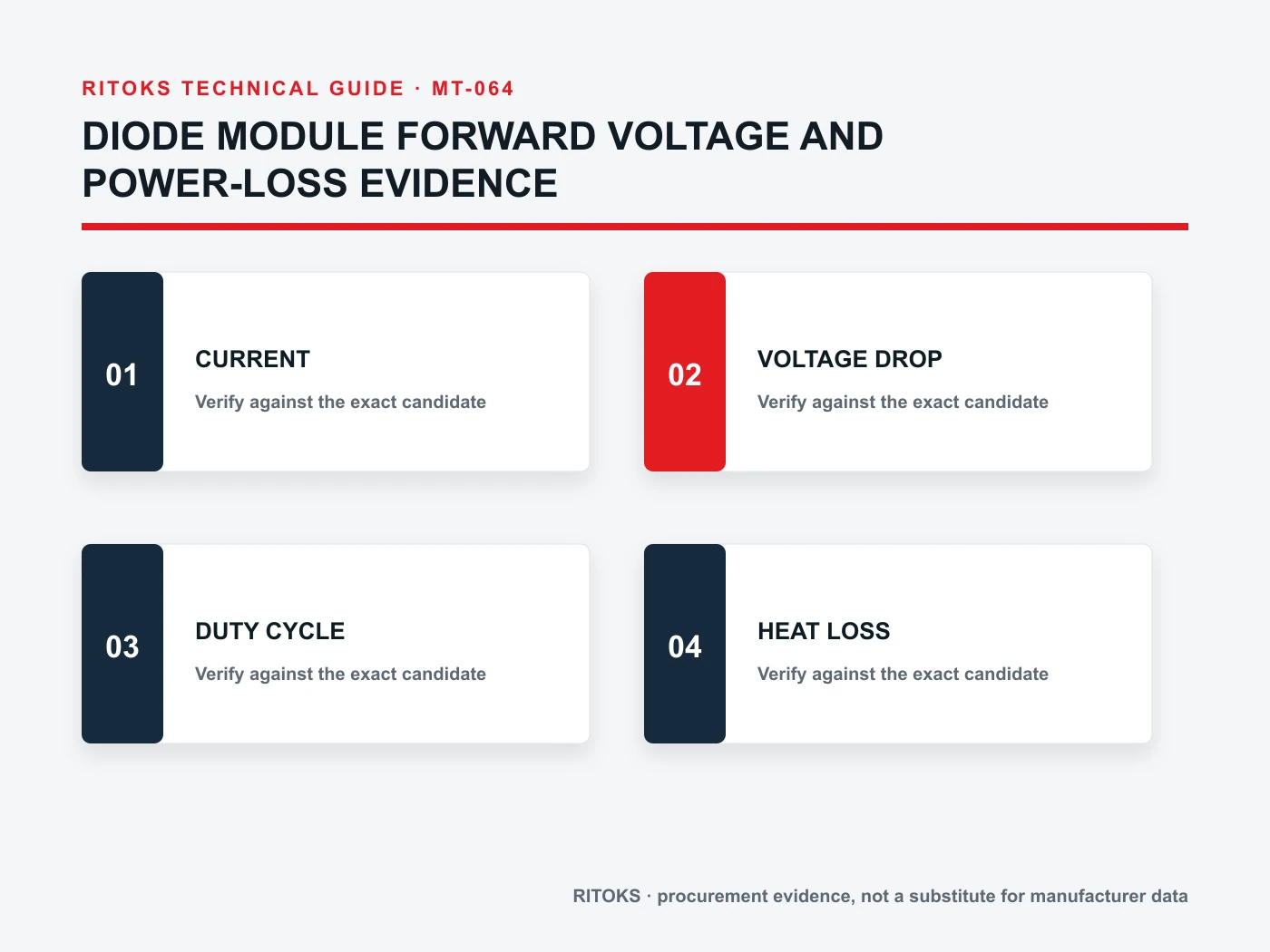
When a forward-voltage figure is quoted, ask at what forward current, junction temperature and pulse condition it was measured. The test method may limit self-heating during measurement. A single headline value without these conditions cannot define average loss in an installed converter.
Check whether the graph is typical and whether limiting values are separately specified. Compare alternative modules using like-for-like conditions. Taking the lowest typical point from one supplier and a maximum point from another creates a misleading comparison. If the information needed to normalize the comparison is absent, list it as an open question.
Look for the distinction between per-chip, per-diode and per-module quantities. For a bridge or dual-diode arrangement, the number of conducting elements changes the total voltage drop and heat. Match the internal schematic and conduction path before summing losses. The commercial term “diode module” does not tell you how many devices are in series in the application path.
Connect electrical loss to the thermal network
Estimated loss feeds a thermal model. The heat must travel from junction through the package, mounting interface and heatsink into the surrounding air or coolant. Obtain exact-model junction-to-case or equivalent thermal data and understand the reference points. The heatsink performance must be measured or specified under airflow and mounting conditions relevant to the installation.
For steady duty, a simplified temperature-rise calculation can screen candidates, but it relies on representative loss and thermal resistance. For changing duty, transient thermal impedance and the timing between pulses may be necessary. Repeated pulses can accumulate heat even when each one is brief. Avoid using a steady-state rating alone to dismiss a repetitive peak.
The interface between module and sink matters. Surface flatness, thermal interface material, mounting pressure and assembly procedure can change contact resistance. Infineon's module installation guide emphasizes material and geometric effects on thermal transfer. The exact proposed module's mounting manual must define the actual process.
Do not confuse forward loss with reverse blocking
Forward-voltage data helps estimate loss when a diode conducts. Reverse-voltage ratings address its ability to block in the opposite direction under specified conditions. One does not replace the other. A module may look attractive on conduction loss while failing the voltage or surge requirements of the circuit.
For a fair candidate review, keep voltage duty, surge duty, current waveform and thermal behavior in separate columns. Each has its own exact-model evidence. If an anti-reverse application is being considered, verify the expected reverse stress and fault scenarios rather than concluding from low forward voltage that the module is suitable.
Make candidate comparisons at the same duty point
| Comparison field | Project input | Model evidence |
|---|---|---|
| Current waveform | Magnitude, duration and repetition | Forward curve or loss model |
| Temperature | Expected junction and ambient range | Temperature-specific forward data |
| Topology | Conducting devices in each state | Internal schematic |
| Thermal path | Interface, sink and airflow | Thermal impedance and mounting guide |
| Other stress | Reverse voltage and surge events | Ratings at relevant conditions |
Document the calculation assumptions and the revision of every datasheet. If a candidate uses a different internal layout or package, the thermal path may change even when the forward curve looks similar. Procurement should avoid substitutions based only on a lower advertised voltage drop.
Validate the installed assembly
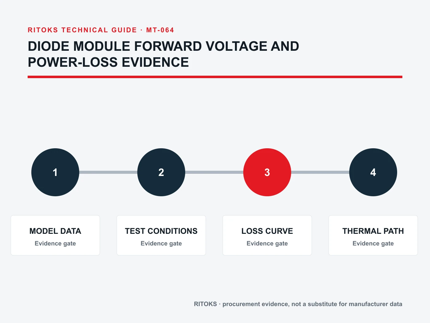
Bench calculations support selection, but an installed temperature test helps check loss and cooling assumptions. Define the current waveform, ambient, airflow, measurement point and time to thermal equilibrium for the test. Use the manufacturer-approved method to relate measured case or sink temperature to junction conditions.
If results diverge from prediction, examine the measured current, internal conducting path, interface application and heatsink airflow before adjusting the model. Record the final assembly process so repeated builds reproduce the verified contact. A prototype that works with an unusually careful hand-applied interface is not sufficient evidence for production.
Keep a record of any design change that affects thermal performance: a different fan, module package, busbar, enclosure wall or mounting material. Even a small mechanical revision can alter airflow or contact quality. Recheck the relevant test rather than assuming the former result transfers intact.
What to do when curves are incomplete
Some product pages list only a nominal current and one forward-voltage point. That is insufficient for a detailed thermal model across a changing waveform. Ask the supplier for the full curve, loss coefficients or an approved application calculation method. Explain the current range and junction-temperature range that the project needs; otherwise the supplier may send a document that still omits the critical region.
If only typical data are available, treat the result as a preliminary screening estimate. Keep an explicit uncertainty allowance and plan a temperature test. Do not label the calculated temperature a guaranteed maximum. If no defensible estimate can be built, hold the selection instead of substituting a convenient curve from another module. Even devices with similar packages may use different chips and internal connections.
How to frame a diode module inquiry
Send the circuit schematic, expected current waveform, conduction duty, blocking-voltage requirement, ambient and cooling plan, package constraints and exact evidence needed. Browse the diode module family to identify commercial options. The MDA common-anode family and MD300A anti-reverse family are different topology starting points, not interchangeable recommendations.
Request exact-model forward curves, thermal data, internal circuit drawing and mounting instructions via RITOKS contact. Ask the supplier to identify which values are typical, limiting or conditional. Only then can the engineer compare thermal behavior at the same application duty.
Frequently asked questions
Does lower forward voltage always mean a cooler module?
Not automatically. Compare devices at the same current waveform and temperature, then account for package thermal path and cooling. A single forward-voltage point does not predict installed junction temperature.
Can I multiply a catalogue voltage by average current?
Only if that approximation is consistent with the manufacturer's method and the current/temperature conditions. A varying waveform often needs integration or a validated loss model rather than one point.
Is a typical curve sufficient for final approval?
Ask for the design basis and any maximum data recommended by the manufacturer. Final approval must account for variation, ambient extremes and the exact mounting method.
Bottom line
Forward voltage supports diode loss estimation only when current waveform, temperature and device path are defined. Match exact-model electrical curves to a thermal path and validate the installed assembly. Leave unsupported loss estimates out of the bill of materials and make the missing evidence explicit.