
Technical Resources · Selection Guide
AC Contactor Selection Guide: Load Duty, Coil Voltage and Auxiliary Contacts
Selecting an AC contactor requires more than matching one current value. The switched load, utilization category, operating voltage, required operational current, coil/control supply, main poles, auxiliary contacts, expected switching frequency and supporting documentation all affect the exact configuration.
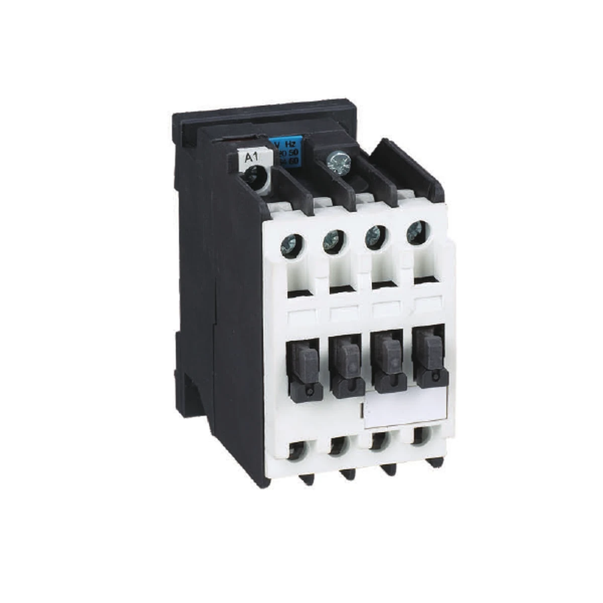
This guide provides an evidence-first specification process for industrial buyers. It does not replace an exact product datasheet, a motor-control coordination study, conductor sizing, short-circuit protection selection or installation instructions.
AC Contactor Selection at a Glance
A useful contactor inquiry separates the power circuit, control circuit and auxiliary functions. Schneider Electric's contactor specification guidance identifies the main contacts, auxiliary contacts and coil as separate elements that must be defined. Its utilization-category documentation also shows why switching duty matters. These sources support general terminology only; their model ratings, accessories and certifications are not RITOKS product data.
| Selection input | What to define or verify |
|---|---|
| Load and switching duty | Describe the load and operating sequence; identify the applicable utilization category from authoritative documentation. |
| Power-circuit voltage | State the operating voltage and phase arrangement for the switched circuit. |
| Operational current / motor output | Use the rating published for the required utilization category and voltage, not a different duty or voltage. |
| Coil/control supply | Specify AC or DC coil supply, voltage and frequency where applicable. |
| Main poles | Confirm the number and normal state required by the circuit architecture. |
| Auxiliary contacts | Specify required NO/NC contacts and any timing or signaling requirement. |
| Operating frequency | Define the expected operations per hour and duty cycle where they affect selection. |
| Environment and enclosure | Provide ambient, mounting, enclosure and installation conditions for exact-model review. |
| Associated devices | Identify overload relays, motor starters, MPCBs, interlocks or other accessories that require verified coordination. |
| Documentation | Request the exact datasheet, ordering code, dimensional drawing, wiring information and required certificates. |
1. Define the Load and Switching Duty
Begin with what the contactor will switch and how it will operate. A resistive load, normal motor starting, reversing, plugging, inching or another switching sequence can place different demands on the main contacts. A contactor rating stated for one utilization category must not be treated as a universal current rating for every load.
For motor-control work, AC-3 and AC-4 are not interchangeable labels. Official manufacturer documentation describes AC-3 around normal squirrel-cage motor starting and switching off during running, while AC-4 covers more severe operations such as plugging, inching or reversing. Record the actual operating sequence, then use the exact manufacturer's rating table for that duty.
The published ZS3TF page provides both AC-3 and AC-4 current fields by model at 380V. These are separate data columns. Do not choose an AC-4 application from the larger AC-3 figure or copy a value between models.
2. Match Operational Current and Voltage to the Exact Duty
Operational current must be read together with operating voltage and utilization category. A motor-output value is also tied to the voltage and model conditions stated in the source. One current number cannot establish suitability across different voltages, loads or switching sequences.
The current ZS3TF industrial AC contactor family lists 17 public models covering 9A to 400A AC-3 rated operational current at 380V. Each row also retains its corresponding AC-4 current, motor output at 400/380V and rated insulation voltage. Use these rows for initial model screening only, then confirm the complete orderable configuration.
Rated insulation voltage is not a substitute for the operating voltage, utilization category or model-specific operational rating. Keep these fields separate in the RFQ and technical review.
3. Separate Power-Circuit Voltage From Coil Voltage
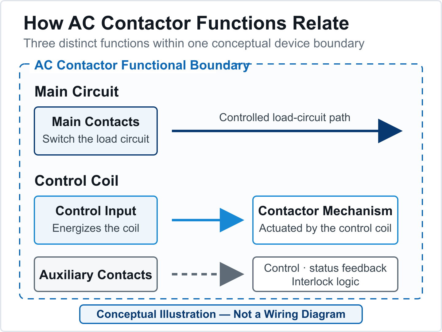
The coil energizes the contactor mechanism, while the main poles switch the power circuit. The coil can therefore require a different voltage from the switched circuit. Specify whether the control supply is AC or DC, its nominal voltage and, for an AC coil, the relevant frequency.
The current ZS3TF public page does not publish a complete coil-voltage ordering map. It lists a coil-voltage tolerance only for ZS3TF46 through ZS3TF56, without publishing every available nominal coil option. Buyers should provide the required control voltage and request the exact model suffix or ordering code rather than infer it from the power-circuit rating.
4. Confirm Main Poles and Auxiliary Contacts
Main poles carry the switched load. Auxiliary contacts are normally used for control, indication, interlocking or feedback functions. Specify the required number of main poles and the required normally open or normally closed auxiliary contacts separately.
The ZS3TF catalog evidence supports a family-level auxiliary arrangement statement of up to 2NO + 2NC, but it does not map that arrangement to every public model. This statement must not be read as a promise that each model includes 2NO + 2NC. State the required arrangement and ask for configuration confirmation.
5. Check Switching Frequency, Endurance and Environment
Applications with frequent operation require more than a current check. Expected operations per hour, electrical duty, mechanical operation, ambient conditions, enclosure temperature and mounting arrangement can affect the exact selection. Request model-specific limits instead of applying one family-wide assumption.
Detailed switching-frequency and endurance values are published on the ZS3TF page only for ZS3TF46 through ZS3TF56. The smaller public models do not carry the same complete performance table. Missing values should remain unclaimed until exact documentation is available.
6. Keep Switching, Overload Protection and Circuit Protection Distinct
A contactor provides controlled switching; it should not be described as automatic overload or short-circuit protection. A thermal overload relay, a motor protection circuit breaker and an upstream circuit-protection device have different functions and evidence requirements.
For a focused comparison of these protection roles, read MPCB vs thermal overload relay vs MCB.
An enclosed motor starter may combine multiple control and protection components in an assembly, but the exact architecture still needs confirmation. Published RITOKS examples include the ZSLE1-D magnetic motor starter and ZS3RU thermal overload relays. Their presence in the same motor-control cluster does not prove compatibility with a selected ZS3TF contactor.
If the project also needs branch or feeder protection, review the separate AC MCB selection guide. Coordination, short-circuit protection and combination ratings require exact manufacturer documentation and should not be created from component names alone.
Published RITOKS AC Contactor Family
The AC Contactors category currently presents the ZS3TF family for industrial circuit switching and AC motor control. The table below is a screening summary, not an automatic model selector.
| Published field | ZS3TF evidence | How to use it |
|---|---|---|
| Public model set | 17 models | Shortlist by exact model row; request the full ordering code. |
| AC-3 current at 380V | 9A to 400A, model-dependent | Use only for the stated voltage and duty. |
| AC-4 current at 380V | Published by model | Use the AC-4 column for the relevant severe-duty requirement; do not substitute AC-3. |
| Motor output | Published by model at 400/380V | Keep the value tied to its exact model and voltage context. |
| Rated insulation voltage | 690V or 1000V, model-dependent | Do not treat it as operational voltage. |
| Coil options | Complete nominal options not published | Provide required coil supply and request confirmation. |
| Auxiliary contacts | Family statement up to 2NO + 2NC | Confirm the exact included or optional arrangement. |
| Dimensions and wiring | Not published on the current page | Request exact drawings and documentation before design-in. |
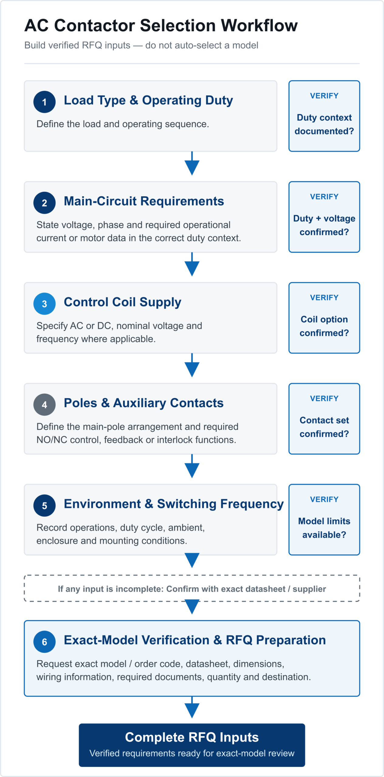
Exact-Model Verification Workflow
- Describe the load and operating sequence.
- Identify the applicable utilization category from authoritative documentation.
- State power-circuit voltage, phase arrangement and required operational current or motor data.
- Specify coil/control supply type, voltage and frequency.
- Define main-pole and auxiliary-contact requirements.
- State expected operating frequency, enclosure and environmental conditions.
- Identify overload, circuit-protection, interlock and starter requirements.
- Request the exact model, ordering code, datasheet, dimensions and wiring information.
Information to Include in an AC Contactor Inquiry
- Application and load type
- Operating sequence and required utilization category
- Power-circuit voltage, phase and frequency
- Required operational current or motor power at the stated voltage
- Coil/control supply type, voltage and frequency
- Main-pole arrangement
- Required auxiliary NO/NC contacts
- Expected operations per hour or duty cycle
- Ambient, enclosure and mounting conditions
- Associated overload relay, starter, MPCB, interlock or accessory requirements
- Required datasheet, drawings, wiring and certificates
- Quantity and destination
Technical References
- Schneider Electric — What information is needed to specify a contactor? — Supports separating main contacts, auxiliary contacts and coil requirements.
- Schneider Electric TeSys Giga — Utilization Categories — Supports the distinction between switching duties and the need for duty-specific ratings.
Frequently Asked Questions
Can I select an AC contactor from motor power alone?
No. Motor power must remain tied to the stated operating voltage, utilization category and exact model. Coil supply, poles, auxiliary contacts, operating frequency and installation conditions may also affect the configuration.
What is the difference between AC-3 and AC-4 contactor ratings?
They represent different motor-switching duties. AC-3 is associated with normal squirrel-cage motor starting and switching off while running. AC-4 covers more severe operations such as plugging, inching or reversing. Use the exact manufacturer's rating for the required duty.
Is the contactor coil voltage the same as the motor voltage?
Not necessarily. The coil belongs to the control circuit and may require a different voltage from the switched power circuit. Specify both separately.
Does every ZS3TF model include 2NO + 2NC auxiliary contacts?
No. The available evidence provides an up-to-2NO + 2NC family statement but does not map that arrangement to every model. Confirm the exact configuration.
Does an AC contactor provide motor overload or short-circuit protection?
A contactor is a switching device. Overload and short-circuit protection require separate, correctly selected and documented devices or assemblies.
What ZS3TF information should be confirmed before ordering?
Confirm the exact model and ordering code, duty, operating voltage and current, coil supply, poles, auxiliary contacts, switching requirements, dimensions, wiring, accessories and required documentation.
Confirm an AC Contactor Configuration for Your Project
Send RITOKS the load duty, power-circuit requirements, coil supply, contact arrangement, operating frequency, documentation needs and quantity for exact-model review.