
Thermal Overload Relays for Motor Protection · Technical Explainer
Thermal Overload Relay Setting Range: Selection and Documentation
A thermal overload relay setting range is the adjustable current interval provided by one exact relay variant. Selection begins with the motor nameplate and application, then checks whether the required setting lies within the documented range under the correct connection and installation conditions. It is not a substitute for short-circuit protection or starter coordination.
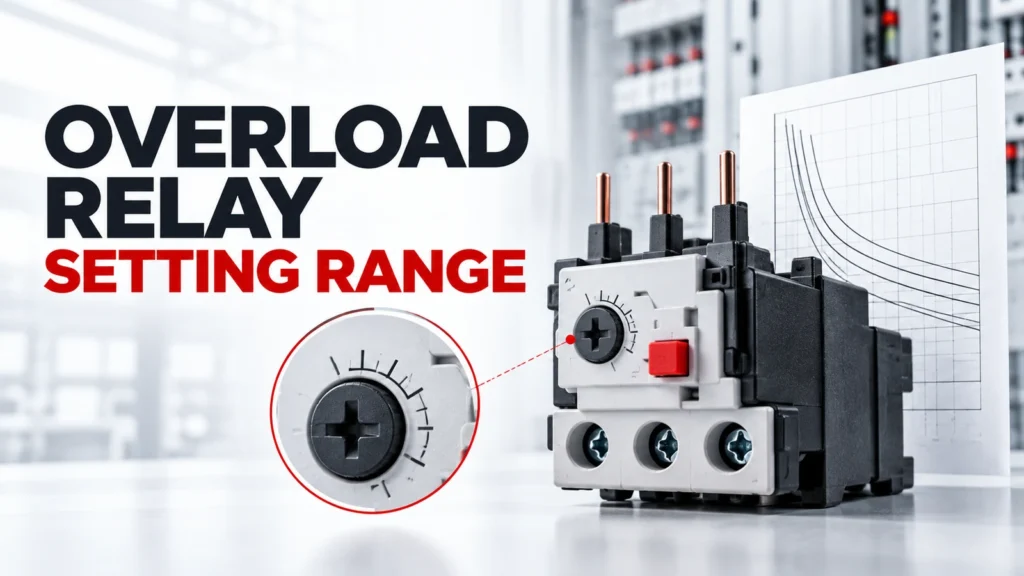
This guide explains the selection and documentation questions around an overload-relay adjustment range. It does not prescribe a final setting, approve a contactor-relay combination or claim that one trip class, reset mode or range applies to every ZS3RU configuration.
Buying Decision at a Glance
| Decision input | Buyer must confirm | Evidence required |
|---|---|---|
| Motor data | Nameplate full-load current, voltage, frequency and connection | Photograph or record of exact nameplate |
| Range | Required setting lies within exact relay adjustment interval | Exact variant table |
| Starting duty | Starting current and acceleration time | Application or starting record |
| Protection behavior | Trip class, phase-loss response and reset mode required | Exact relay documentation |
| Coordination | Contactor, upstream protection and fault duty | Manufacturer coordination evidence |
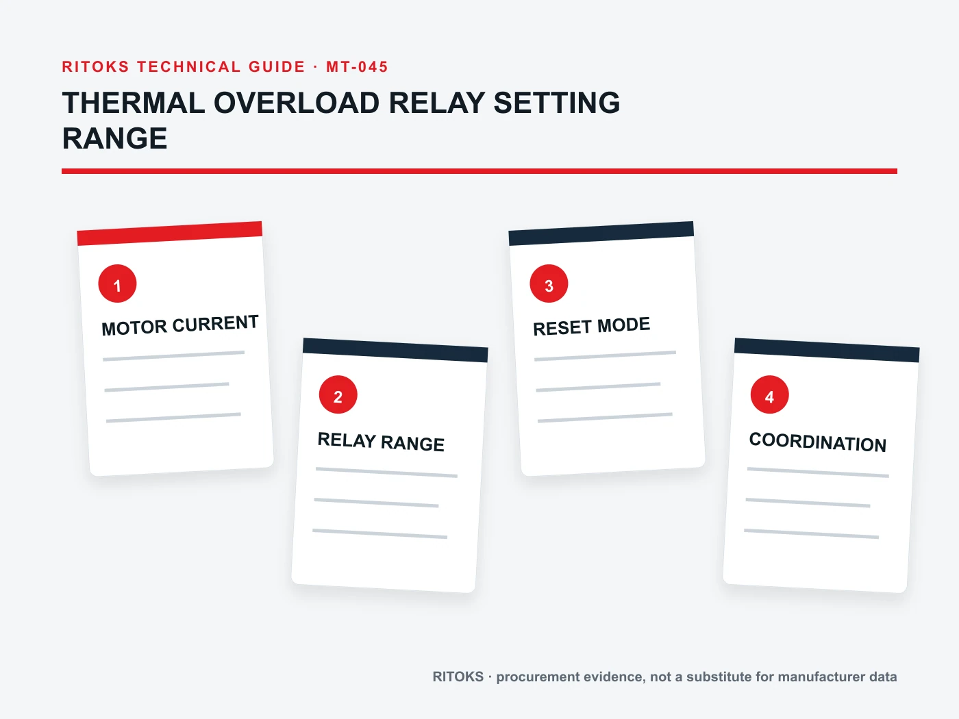
Begin With the Motor Nameplate and Connection
Record the exact motor full-load current for the actual voltage, frequency and winding connection. A motor with multiple voltage or connection options may show more than one current. The chosen value must match how the machine will be supplied, not the largest or smallest number on the plate.
Also record service factor or other manufacturer instructions that affect overload protection. Do not apply a generic multiplier unless the responsible motor and relay documentation supports it. The setting decision belongs to the project protection design and must remain traceable.
Match the Required Setting to One Exact Range
Manufacturers commonly offer neighboring relay variants with overlapping or adjacent adjustment intervals. Select an exact order code whose documented range contains the required setting. Do not assume that a family headline spanning many amperes describes one adjustable device.
Avoid placing the intended setting at a boundary without checking accuracy, tolerance and application guidance. A range that merely includes the number may still be wrong if the relay is incompatible with the contactor, mounting method, motor duty or required trip behavior.
Check Starting Time and Trip Class
The relay must allow the intended motor to accelerate without nuisance tripping while responding to sustained overload according to the protection design. Record the motor starting method, expected starting current, acceleration time, starts per hour and load inertia.
Trip-class terminology must be read from the exact relay documentation and coordination method. A longer starting load does not justify an arbitrary slower class, because that can change motor protection. Ask for the trip characteristic and identify who is responsible for approving the protection setting.
Separate Overload From Short-Circuit Protection
A thermal overload relay addresses motor overload conditions within its stated function. It does not automatically provide the short-circuit interruption required for the circuit. The starter record should identify upstream protective devices and the exact coordination evidence for the proposed combination.
Breaking capacity, backup protection and type of coordination cannot be inferred from the relay setting dial. Preserve the manufacturer table or report that covers the exact contactor, relay, protective device, voltage and fault condition. Similar frame sizes are not proof of a tested combination.
Document Reset, Contacts and Installation Conditions
State manual or automatic reset requirements, auxiliary contact use and the control action after a trip. Automatic restart can create machine hazards, so reset behavior must follow the control-system risk assessment and applicable project rules.
Ambient temperature, enclosure heating, mounting and proximity to other heat sources may influence relay performance or compensation. Use exact instructions and record the installed location. During commissioning, document the set value, sealing or access control, test method and responsible approver.
Build an Exact-Configuration Evidence File
Create one review sheet for the proposed Thermal Overload Relay order code. Put project inputs in one column and supplier evidence in the other. Preserve the exact datasheets, drawings, curves, tables and manuals used in the decision, including their revision or retrieval date. A category page can establish family context, but an exact rating, setting, protocol or connection claim must trace to the quoted configuration.
Check that every accepted value describes the same orderable item. Similar housings and family names can hide different circuits, supplies, terminals, controls, mounting details or accessories. Do not combine a family maximum from one variant, a drawing from another and an optional feature from a third. Keep unresolved fields visible in the technical comparison.
Control Changes During Sourcing
Freeze the application record while suppliers respond. If the load, voltage, environment, duty, enclosure, control method or required output changes, issue a revised record and ask each supplier to reconfirm the candidate. Otherwise quotations can appear comparable while answering different technical requirements.
A proposed substitute returns to the same evidence gate. Matching dimensions, a similar product photograph or one equal headline rating is not enough. The substitute must satisfy the required functions and conditions using its own exact documentation.
Common Procurement Errors
- Selecting a Thermal Overload Relay from one headline value while leaving the application context undefined.
- Using a curve, setting table, register map or connection diagram from a neighboring model.
- Treating a family maximum or ideal test condition as the application operating point.
- Assuming included accessories, controls and system functions from the product name or photograph.
- Approving a substitution without reopening the technical evidence review.
A family-wide adjustment span is not the range of one relay. Match the actual motor nameplate current and winding connection to one order code, and check trip class, reset and contact arrangement separately.
How to Compare Supplier Offers
| Comparison point | Required evidence | Do not accept |
|---|---|---|
| Motor current | Exact nameplate value for actual connection | Generic motor kW table alone |
| Range | Exact order code contains required setting | Family-wide minimum and maximum |
| Starting duty | Current and acceleration time recorded | “Normal start” without evidence |
| Trip behavior | Class and curve documented | Dial range treated as complete protection |
| Coordination | Exact tested device combination | Same-brand assumption |

Normalize every Thermal Overload Relay offer to the same application record. Keep document revisions, test conditions and open questions beside each value. A proposal can remain commercially interesting while technically incomplete, but missing evidence should stay visible until resolved.
Decision Workflow
- Record motor nameplate and actual electrical connection.
- Define starting method, acceleration time and operating duty.
- Choose an exact relay range around the required setting.
- Verify trip class, reset and phase-loss behavior.
- Confirm contactor and upstream protective-device coordination.
- Record approved setting and commissioning evidence.
Start with motor nameplate current at its installed connection and expected starting behavior. Choose an exact documented relay range, then verify trip class, contactor fit, reset mode and upstream short-circuit protection before quotation.
RFQ Preparation Checklist
A useful RFQ for overload relay setting range is concise enough to answer and complete enough to prevent silent assumptions. Identify unknown values as questions and require an exact orderable code rather than a generic family recommendation.
- Motor manufacturer, model and nameplate data
- Supply voltage, frequency and winding connection
- Full-load current and starting profile
- Required adjustment range and trip-class evidence
- Manual or automatic reset and auxiliary contacts
- Contactor and upstream protection details
- Coordination documents, quantity and destination
Request the current datasheet and manual revisions and the scope of any certification, compatibility or performance claim. Record quantity and destination after the technical inputs so commercial terms do not obscure unresolved engineering questions.
Stop Conditions Before Order Release
Do not release the order while a critical application input is unknown, the quoted model is ambiguous, a required claim is supported only by another product document, or installation conditions fall outside the available evidence. These are engineering gaps, not editorial details.
The approval record should state what the selected item does, what remains outside its scope and which exact documents support the decision. If the application or candidate changes, reopen the affected checks rather than carrying the previous conclusion forward.
Frequently Asked Questions
Should the relay be set from motor power alone?
No. Use the exact motor current and the applicable manufacturer and protection-design method.
Does an overload relay replace a circuit breaker or fuse?
No. Overload and short-circuit functions must be addressed in the complete coordinated starter design.
Can any relay in the current range fit any contactor?
No. Mechanical fit, electrical compatibility and coordination require exact manufacturer evidence.
Related RITOKS Products and Guidance
Use these destinations as separate category, product and guidance records. A contextual link does not claim interchangeability, coordination, compatibility or approval for a particular application.
Thermal Overload Relay product category
Overload relay vs circuit breaker
Technical References
These primary standards or manufacturer sources support only the general concepts identified below. Their product values, diagrams, approvals and tested combinations do not transfer to RITOKS products.
ABB, Contactors and Overload Relays Guide
Supports the relationship between motor data, overload-relay selection, trip class, adjustment and starter coordination. ABB combinations and settings do not apply to RITOKS products.
ABB, Control Catalog: IEC Manual Motor Starters
Supports treating motor protection and starter selection as coordinated device and application decisions. ABB ratings and combinations are not evidence for RITOKS models.
Request an Exact-Model Review
Send the application requirements, exact documentation questions, quantity and destination through the RITOKS contact form. An RFQ requests an exact-model review; this guide does not approve a wiring design, protection setting, installation or automatic substitute.