
Power Module Heatsinks · Selection Guide
Power Module Heatsink Selection Guide: Loss, Thermal Resistance and Airflow
A power-module heatsink is selected from a thermal path, not from module current alone. The designer needs semiconductor loss at the real duty, an allowed junction-temperature objective, interface data, heatsink performance under the installed airflow and a mechanical arrangement that preserves contact. Missing any link can make an apparently generous extrusion inadequate.

This guide explains the evidence chain required to select a heatsink for SCR, rectifier or other power modules. It does not calculate a heatsink for an unknown semiconductor, publish transferable thermal-resistance values or approve a mounting method without exact device and heatsink documents.
Decision Inputs at a Glance
| Decision input | Buyer must confirm | Evidence required |
|---|---|---|
| Heat generation | Conduction and switching loss at the design duty | Exact semiconductor loss data or validated calculation |
| Temperature boundary | Maximum junction objective and worst local ambient | Device limits and project criterion |
| Interface path | Case, thermal interface material and contact condition | Mounting instruction and interface data |
| Heatsink performance | Thermal behavior at actual orientation and airflow | Exact heatsink curve or validated model |
| Mechanical fit | Footprint, hole pattern, flatness, fasteners and clearance | Dimensioned assembly drawing |
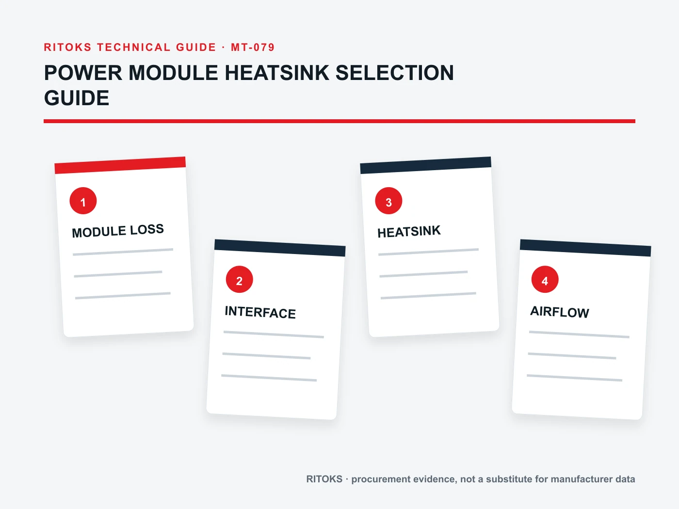
Begin With Semiconductor Loss
Current rating is not a direct heat value. Determine conduction, switching and other relevant losses using the exact device characteristics and the actual waveform, duty and control method.
Document who owns the loss calculation and preserve its inputs. If the semiconductor or duty changes, the heatsink review must be reopened instead of retaining the old result by default.
Build the Complete Thermal Resistance Chain
The path normally includes junction-to-case behavior, the interface between module and sink, the heatsink itself and the air or other cooling medium. Each part has its own conditions and uncertainty.
Do not subtract catalog temperatures without checking definitions. Use one consistent thermal model and units, and distinguish manufacturer limits from the project’s chosen design margin.
Treat Interface Quality as an Engineering Input
Flatness, surface condition, thermal interface material, application method, mounting force and tightening sequence influence contact performance. Follow the semiconductor and heatsink instructions that apply to the exact assembly.
Adding more interface material is not automatically safer because excess thickness can increase resistance. The approved material and process should be repeatable in production and service.
Use Heatsink Data for the Installed Airflow
Natural-convection performance depends on orientation, fin spacing and surrounding clearance. Forced-air performance depends on flow distribution, pressure capability, obstructions and where air temperature is measured.
A fan free-air value is not the airflow through a loaded heatsink channel. Evaluate the complete path and use performance evidence whose test arrangement is relevant to the proposed installation.
Verify Mechanical Compatibility
Check module footprint, mounting holes, terminal access, creepage and clearance needs, base thickness and available fastener depth. The electrical layout must not force a poor thermal contact or block fins.
Create an assembly drawing that identifies the module, sink, interface, fasteners and orientation. This prevents the quotation from mixing compatible-looking parts that have not been reviewed together.
Plan Verification and Field Maintenance
Prototype or thermal testing may be needed when calculations contain uncertain inputs, unusual duty or restricted airflow. Define sensor locations and acceptance criteria before the test.
Dust, fan degradation and blocked clearances can raise temperature over time. The maintenance plan should preserve the airflow and inspection access assumed by the selection.
Build an Exact-Model Evidence File
Build the heatsink approval record around the exact module, mounting interface, available space and cooling arrangement. Match the proposed heatsink to its dimensioned drawing and the relevant thermal evidence under stated test or operating conditions. Record the mounting and airflow assumptions alongside the document revision. A compatible footprint or a product-family page cannot establish the thermal performance of the complete assembly.
Check that every accepted statement describes the same orderable item. Similar housings can contain different circuits, terminals, materials, firmware or accessories. Do not combine a maximum from one variant, a drawing from another and a feature from a third. Mark unresolved fields explicitly so they remain visible during engineering and commercial review.
Keep Project Inputs Separate From Product Evidence
The project team defines the application: source, load, duty, environment, controls, mechanical limits and required functions. The supplier identifies an exact Power Module Heatsink and supports it with exact documents. Neither side should fill a gap by inference from appearance, a shared family name or one matching headline value.
Freeze the application record while quotations are compared. If the circuit, load, duty, environment, enclosure, thermal method or required output changes, issue a revised record and ask each supplier to reconfirm the candidate. Otherwise apparently comparable quotations may be answering different technical requirements.
Common Procurement Errors
- Selecting Power Module Heatsink from one headline rating while the application context remains incomplete.
- Using a circuit, curve, terminal drawing or performance claim from a neighboring model.
- Treating a family page or product photograph as exact technical evidence.
- Assuming an accessory, system function or coordination result is included without documentation.
- Approving a substitute without repeating the electrical, thermal, mechanical and evidence review.
Resolve these gaps before comparing price and lead time. The reviewer should be able to trace every accepted statement either to the project requirement or to the exact candidate document. A proposal may remain commercially interesting while technically incomplete, but missing evidence must not disappear inside the quotation.
How to Compare Supplier Offers
| Comparison point | Required evidence | Do not accept |
|---|---|---|
| Exact identity | Full orderable code and variant description | Family name alone |
| Application match | Response against the frozen project inputs | Generic suitability statement |
| Technical evidence | Current exact-model documents with revision | Screenshot or neighboring-model page |
| Delivered scope | Included accessories, interfaces and documents | Undefined “standard package” |
| Open questions | Visible deviation and clarification list | Silence treated as compliance |
| Substitution | Fresh review against every requirement | “Equivalent” based on appearance |
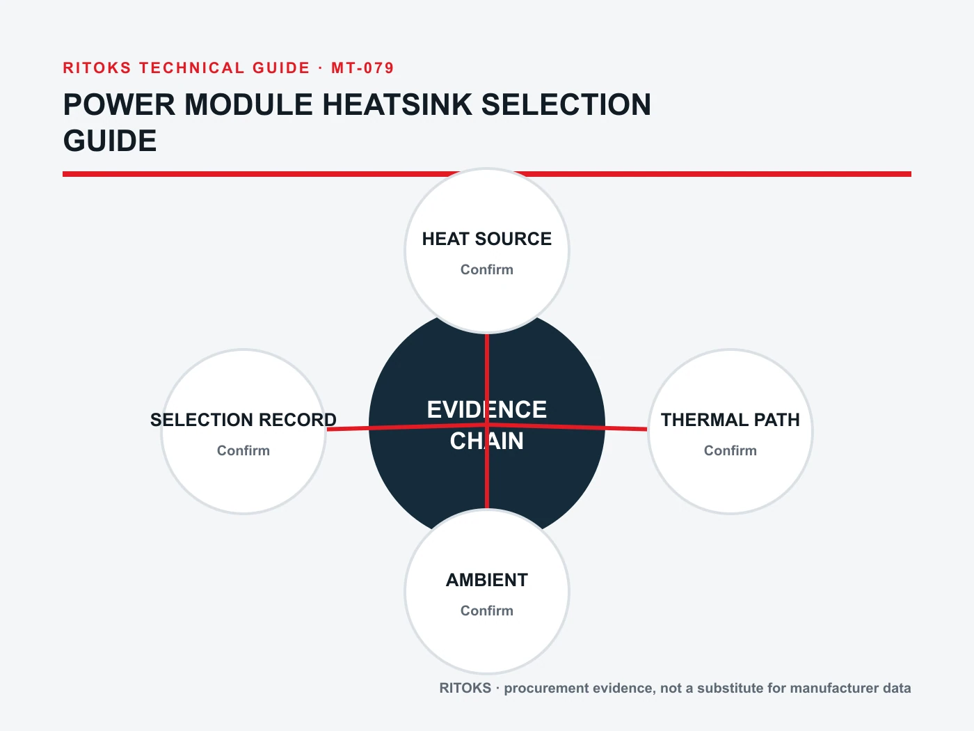
Normalize every Power Module Heatsink offer to the same application record. Keep document revisions, test conditions, included accessories and open questions beside each value. This makes differences in delivered scope visible and prevents a lower-cost but narrower offer from appearing equivalent to a complete solution.
Decision Workflow
- Freeze the application architecture and operating case.
- Record environmental, thermal and mechanical constraints.
- Identify the required Power Module Heatsink function without assuming a model.
- Request a complete order code and exact supporting documents.
- Compare every claim with its conditions and definitions.
- Resolve deviations and coordination questions before commercial approval.
- Archive the accepted evidence with the final bill of materials.
Stop the review when a critical application input is unknown, the quoted model is ambiguous, a required claim is supported only by another manufacturer or another order code, or the installation falls outside the available evidence. These are engineering gaps, not editorial details.
RFQ Preparation Checklist
A useful RFQ for power module heatsink selection guide is concise enough to answer and complete enough to prevent silent assumptions. Identify unknown values as questions and require a full orderable code rather than a generic family recommendation.
- Device loss
- Interface
- Sink path
- Air path
- Ambient
- Module footprint
- Flatness
- Fastening
- Orientation
- Service clearance
- Quantity, destination and required document language
Request the current datasheet revision and the exact scope of any certification, compatibility, coordination or performance claim. Record quantity and destination after the technical inputs so commercial terms do not obscure unresolved engineering questions.
Handoff From Engineering to Purchasing
Engineering approval should identify the exact Power Module Heatsink code, accepted document revisions, unresolved deviations and the application record used for the decision. Purchasing can then compare commercial offers without silently changing the technical basis. If a supplier proposes another code, different accessory or revised configuration, route it back through the same review instead of treating it as an administrative substitution.
Keep the approved evidence with the purchase order and final bill of materials. Receiving and production teams need enough information to recognize the accepted item and to stop when labeling, terminal arrangement, accessories or documentation differ. This handoff also gives maintenance teams a traceable starting point for replacement decisions rather than relying on a photograph, an old invoice description or one headline rating.
Frequently Asked Questions
Can a heatsink be selected from module current rating?
No. Use semiconductor loss at the actual duty and the full thermal path.
Is a lower catalog thermal resistance always better?
Only when the definition and test conditions apply to the installed orientation and airflow.
Can any thermal compound be used?
Use an interface material and process supported for the exact module and assembly.
Related RITOKS Products and Guidance
These links provide published product-family context only. A contextual link does not claim interchangeability, compatibility or an approved system combination.
Power Module Heatsink product category
Published RITOKS Power Module Heatsink product page
Published RITOKS Power Module Heatsink product page
Related published RITOKS technical guide
Technical Reference
The following source supports only the general engineering concept stated in this guide. Its product ratings, circuit diagrams, approvals and coordination results do not transfer to RITOKS products.
Infineon, Thermal design and mounting guidance for power semiconductor modules
Supports treating loss, thermal interfaces and mounting as one design chain; Infineon values do not transfer to RITOKS products.
Request an Exact-Model Review
Send the application requirements, exact-document questions, quantity and destination through the RITOKS contact form. An RFQ requests an exact-model review; this guide does not approve a circuit, installation or automatic substitute.