
Current Transformers · Technical Explainer
Current Transformer Accuracy Class and Burden: Verification Guide
Current transformer accuracy class and burden describe a measurement system, not a standalone quality score. A CT specified for a particular class is assessed under defined conditions. The connected meter, cable and terminals impose a real secondary burden that must fit the evidence for the exact CT.
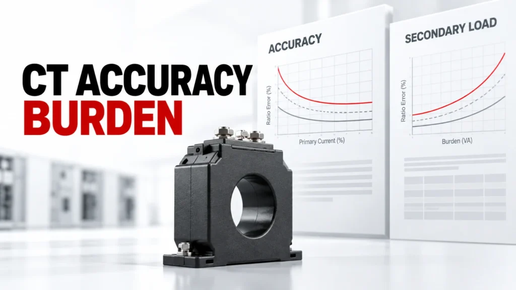
This guide explains the questions a buyer should put in the technical file. It does not assign universal accuracy to a CT family or prescribe a ratio from the equipment name alone.
Decision Inputs at a Glance
| Review area | What the buyer records | Evidence to request |
|---|---|---|
| Primary side | Expected current range and conductor arrangement | Load record and installation drawing |
| Secondary side | Output expected by receiving device | CT and meter input documents |
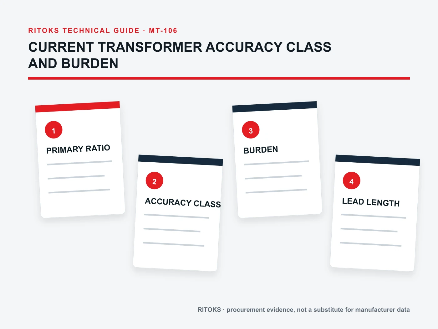
| Burden | Meter input plus lead and connection contribution | Circuit estimate and exact CT data |
| Accuracy | Required class under relevant conditions | Exact CT datasheet and test basis |
Define the measurement purpose
A monitoring display, energy accounting function and control input may demand different evidence. State what the reading will be used for, its relevant operating range and the consequences of error. The CT ratio and class should follow that purpose.
If the circuit rarely operates near its nominal maximum, consider performance over the actual range rather than selecting from one full-scale number. Ask the supplier for the exact conditions to which its accuracy statement applies.
Understand class as a conditional statement
An accuracy class describes performance under a defined standard or test basis. It is not a promise that the installed meter will show that error under every current, frequency, temperature or burden.
Read the complete CT datasheet, including the specified output, rated burden and class conditions. Do not transfer a class label from one variant, core size or ratio to another.
Calculate the complete secondary burden
The receiving meter input is only part of the load seen by the CT secondary. Lead resistance, terminals and other connected devices can contribute. Longer runs and multiple instruments may materially change the burden.
Document the secondary route and the actual devices attached to it. Compare the resulting burden with the exact CT evidence; if the circuit changes, update the assessment. Avoid treating a catalog burden value as a measurement of the installed circuit.
Match ratio and output to the meter
The CT primary ratio should represent the expected current range, while the secondary output must match the meter input. A number in the product title does not prove the output of every order code or compatibility with every panel meter.
Obtain both connection diagrams and the meter configuration method. Record any programmable ratio in the commissioning file so the display and exported data use the same scaling.
Check physical installation
Solid-core and split-core devices may solve different installation constraints. Confirm conductor or busbar dimensions, window space, mounting access and orientation. The choice of housing also affects how the secondary circuit can be routed and inspected.
If retrofitting a live panel is proposed, the work method needs a separate safety review by qualified personnel. Do not infer installation permission from the split-core label.
Verify the system, not only the CT
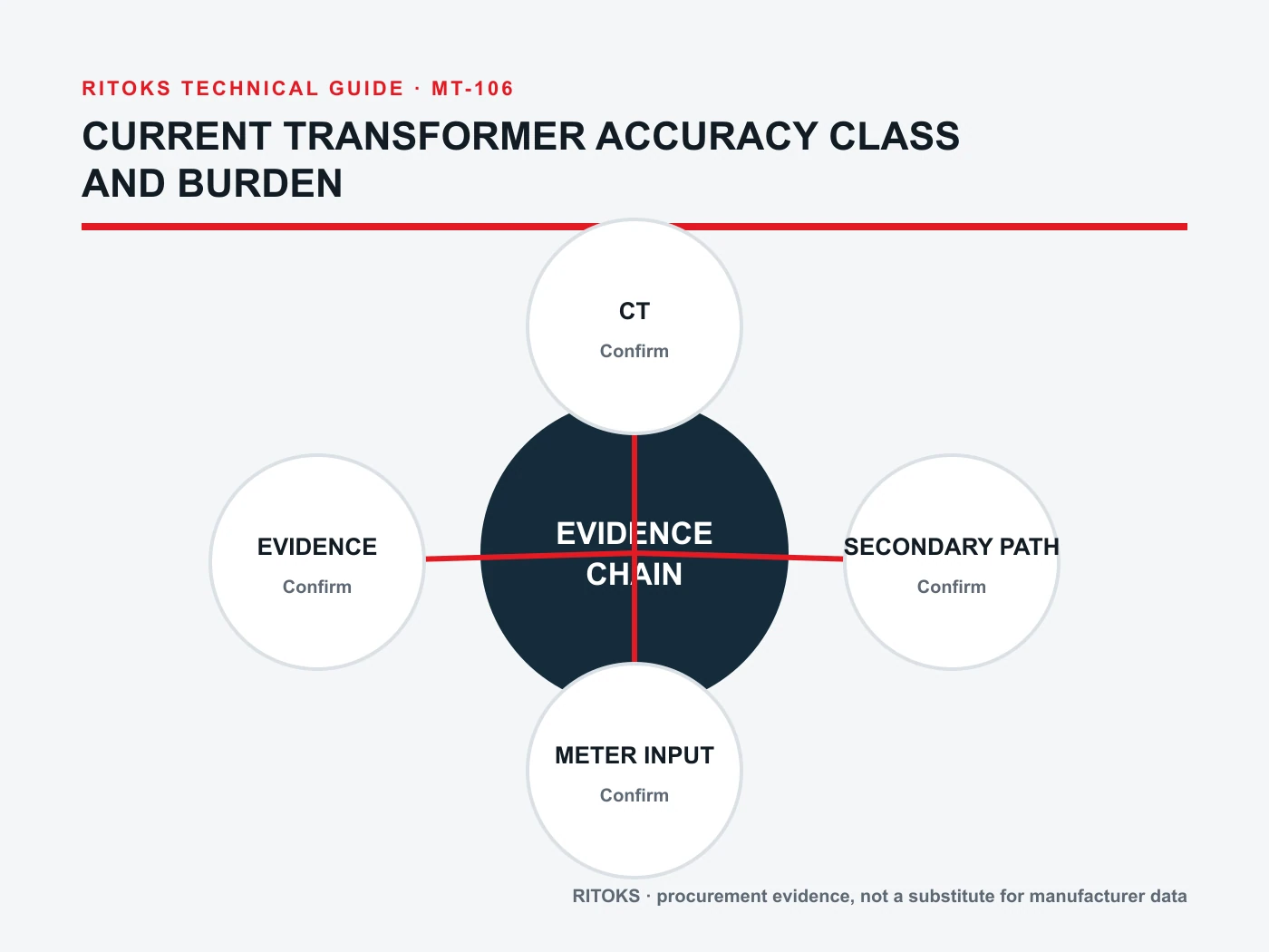
A CT, meter, wiring path and configured ratio form one measurement chain. Commissioning should check polarity or direction where relevant, expected response and scaling under known conditions.
Keep the as-built secondary diagram and configuration alongside the selected CT order code. This makes it possible to diagnose a discrepancy between the meter display and another measurement without guessing which component changed.
Request evidence that matches the quoted item
Ask for exact ratio, output, rated burden, accuracy basis, physical drawing and installation instructions for the proposed CT. Separate what the product page shows from what the order-specific documents prove.
A proposal remains open if the accuracy class is visible but the burden or operating conditions are not. Resolve those fields before approval, especially when the reading supports a commercial or control decision.
Build an Exact-Model Evidence File
A category or product-family page helps locate relevant options; it does not by itself approve one variant. For current transformers, keep the full proposed order code, current datasheet, terminal or mounting drawing, operating instructions and any project calculation together. Read the conditions attached to each rating or function. If the evidence belongs to a neighboring model, request the correct document instead of carrying the claim across.
The project team owns the system inputs and acceptance criteria. The supplier owns the evidence for the offered item. In the technical review, place each mandatory requirement beside the exact document and revision that answers it. Mark a missing field as open, conditional or unsupported. This creates a traceable decision and prevents a favorable headline value from hiding an incompatible connection or installation condition.
Compare Complete Offers
| Item | Record in the comparison | Reason |
|---|---|---|
| Orderable item | Full code, variant and included accessories | Prevents family-level assumptions |
| Application match | Written response to each project input | Keeps exceptions visible |
| Documentation | Datasheet, drawing, instructions and revisions | Links claims to the offered item |
| Open points | Owner and due date for clarification | Avoids silent acceptance |
Use the same project brief for every quotation. Commercial terms such as price and lead time can be compared once the technical scope is normalized. Do not treat omitted accessories, unsupported ratings or an unresolved wiring assumption as equivalent to a documented offer. If an alternative is proposed, ask which inputs change and repeat the affected review.
Review Installation and Acceptance
Before installation, confirm that the delivered label, complete code and accessories match the approved record. Compare terminals, mounting, conductor access and any stated orientation with the exact instructions. A product that appears physically similar to the approved version may still have a different electrical configuration, control option or test basis.
Plan an as-built check that addresses the project's real risks. This may involve wiring against the approved diagram, functional response, measurements under representative operating states and confirmation of any communication or alarm feature. Record the conditions and results. The acceptance plan should come from the application and supplier evidence, not from a generic article checklist.
Request for Quotation Checklist
- Identify the circuit, equipment and location that current transformers must serve.
- Attach the system drawing and operating states that define the application.
- Record primary range and its source document.
- Record secondary output and its source document.
- Record accuracy class and its source document.
- Record rated burden and its source document.
- Confirm the exact-model evidence for meter input.
- Confirm the exact-model evidence for lead length.
- Confirm the exact-model evidence for connection.
- Confirm the exact-model evidence for test record.
- Request the full order code, accessories, drawings and data-sheet revision.
- Ask for exclusions, assumptions, substitutes and unresolved engineering points.
The RFQ should be specific enough for a supplier to answer without inventing missing project values. If an essential input is not yet known, label it as a question and identify who will determine it. Do not turn an assumption into a rating, a compliance claim or an approved installation method.
What Changes the Decision
A decision can change when the source arrangement, load behavior, environment, installation geometry or required function changes. Revisit the selected current transformers whenever one of those inputs moves outside the approved brief. Recheck the order code and the exact evidence affected by the change; do not rely on a previous approval for a circuit that now asks the component to do different work.
Keep a short revision history of the project brief, supplier response and accepted exception list. This record helps engineering, purchasing and commissioning work from the same version. It is especially useful when a quotation is revised, a substitute is offered or the panel design changes after the first comparison.
Questions to Resolve Before Approval
Ask who owns each remaining technical question for the proposed current transformers. The buyer should confirm the system inputs and installation constraints; the supplier should confirm the exact item, included options and applicable documentation. Put the answer and document revision beside the question. An unanswered point should remain visible in the comparison rather than being converted into an assumed feature.
When a quotation offers an alternative, ask for a written explanation of the changed circuit, mounting or performance basis. Review any new drawing with the project engineer and record whether the proposed change is acceptable. A substitution is a new technical decision even if it appears commercially equivalent. This is especially important when multiple suppliers use similar family labels for different configurations.
Frequently Asked Questions
Does a higher accuracy class guarantee an accurate installation?
No. The connected burden, current range, meter input, wiring and configuration also matter.
Can I connect any CT to any panel meter?
No. Verify secondary output, input requirements, ratio configuration and wiring.
Is rated burden the same as actual burden?
No. Rated burden is a product condition; actual burden is created by the installed secondary circuit.
Relevant RITOKS Pages
For product-family context, see Electrical Measurement & Monitoring. The related published product pages include Bh 0 66 60i Current Transformer 200 5a 1500 5a, Dp Series Split Core Current Transformer, Gta20l Precision Current Transformer 10a 100a. Use their current exact-model documents when comparing a proposed item.
For an application-specific quotation, send the project brief to RITOKS with the diagrams and open questions above.