
Solid State Relays for Electronic Switching · Comparison
Zero-Cross vs Random-Turn-On SSRs: Application Boundaries
The difference between zero-cross and random-turn-on solid state relays is not a quality ranking. It is a switching-timing choice that must fit the load, the control objective and the power circuit. A useful comparison therefore starts with what must happen at turn-on, not with a preference for one label.
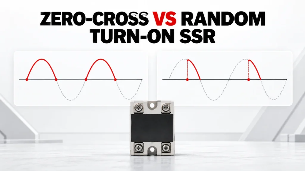
This guide explains the application boundary between zero-cross and random-turn-on AC solid state relay switching. It does not select a relay for an unknown load, state that either switching mode is universally better, or transfer trigger behavior and ratings between product variants.
Decision Inputs at a Glance
| Decision input | Buyer must confirm | Evidence required |
|---|---|---|
| Load behavior | Resistive, inductive, transformer, lamp or other documented characteristic | Load datasheet and inrush profile |
| Control objective | Cycle-based regulation, phase-related control or simple on/off duty | Control sequence and timing requirement |
| Output circuit | AC output type and permitted operating envelope | Exact SSR datasheet |
| Switching cadence | Expected operations and minimum on/off timing | Machine duty record |
| Thermal design | Loss, mounting surface, airflow and ambient | Exact-model loss data and thermal calculation |

Understand What the Trigger Label Describes
A zero-cross output is intended to begin conduction near a suitable point in the AC waveform after the control input is asserted. A random-turn-on output can respond without waiting for that crossing. The exact behavior, delay and conditions belong to the model datasheet.
These labels describe an output-switching behavior, not the entire relay. The buyer must still verify output type, load compatibility, control input, off-state behavior, thermal limits and mechanical arrangement.
Begin With the Load, Not the Relay
Record the load technology, steady-state current, starting or inrush behavior and any transformer or capacitive input stage. Two loads with the same nominal power can present very different switching conditions.
Ask the load manufacturer or equipment designer for a usable electrical profile. If the load behavior is unknown, mark the SSR selection incomplete rather than treating “resistive” or “inductive” as a guess.
Clarify the Control Objective
Simple temperature control, burst control, rapid cycling and phase-related control do not impose the same timing requirement. State whether the controller merely commands on and off or depends on conduction beginning at a particular point in the waveform.
Confirm that the controller output and the SSR input form a documented interface. Input voltage range, required current, logic polarity and response behavior must all be checked on the exact pair.
Treat Switching Mode and Protection as Separate Decisions
The trigger mode does not by itself solve short-circuit, overload or transient protection. Define the protective architecture for the semiconductor output and verify it through the applicable device and fuse documentation.
Do not infer coordination from a shared current label. Semiconductor protection depends on conditions and evidence that must identify the exact relay, protective device and circuit assumptions.
Complete the Thermal Design
An SSR dissipates heat while carrying load current. The acceptable current therefore depends on junction limits, loss data, thermal interfaces, mounting surface, ambient temperature and airflow.
Use the exact-model curves or loss information to build the thermal calculation. A current headline without its thermal conditions is a catalog-navigation value, not final approval evidence.
Check Off-State and Failure Behavior
Review leakage, minimum load implications, dv/dt susceptibility, isolation information and the expected failure response using the exact documentation. These factors can affect indication circuits, sensitive loads and safe maintenance.
The machine risk assessment should define the required safe state and whether additional isolation or monitoring is needed. Do not assume a semiconductor relay provides a visible or safety isolation function.
Build an Exact-Model Evidence File
Create one approval record for the proposed Solid State Relay order code. Put each project requirement beside the supplier document that answers it. Preserve the exact datasheet, dimensioned drawing, circuit diagram, performance curve or application note used, including its revision or retrieval date. A category page establishes family context but cannot prove an exact rating, terminal arrangement, optional feature or system combination.
Check that every accepted statement describes the same orderable item. Similar housings can contain different circuits, terminals, materials, firmware or accessories. Do not combine a maximum from one variant, a drawing from another and a feature from a third. Mark unresolved fields explicitly so they remain visible during engineering and commercial review.
Keep Project Inputs Separate From Product Evidence
The project team defines the application: source, load, duty, environment, controls, mechanical limits and required functions. The supplier identifies an exact Solid State Relay and supports it with exact documents. Neither side should fill a gap by inference from appearance, a shared family name or one matching headline value.
Freeze the application record while quotations are compared. If the circuit, load, duty, environment, enclosure, thermal method or required output changes, issue a revised record and ask each supplier to reconfirm the candidate. Otherwise apparently comparable quotations may be answering different technical requirements.
Common Procurement Errors
- Selecting Solid State Relay from one headline rating while the application context remains incomplete.
- Using a circuit, curve, terminal drawing or performance claim from a neighboring model.
- Treating a family page or product photograph as exact technical evidence.
- Assuming an accessory, system function or coordination result is included without documentation.
- Approving a substitute without repeating the electrical, thermal, mechanical and evidence review.
Resolve these gaps before comparing price and lead time. The reviewer should be able to trace every accepted statement either to the project requirement or to the exact candidate document. A proposal may remain commercially interesting while technically incomplete, but missing evidence must not disappear inside the quotation.
How to Compare Supplier Offers
| Comparison point | Required evidence | Do not accept |
|---|---|---|
| Exact identity | Full orderable code and variant description | Family name alone |
| Application match | Response against the frozen project inputs | Generic suitability statement |
| Technical evidence | Current exact-model documents with revision | Screenshot or neighboring-model page |
| Delivered scope | Included accessories, interfaces and documents | Undefined “standard package” |
| Open questions | Visible deviation and clarification list | Silence treated as compliance |
| Substitution | Fresh review against every requirement | “Equivalent” based on appearance |
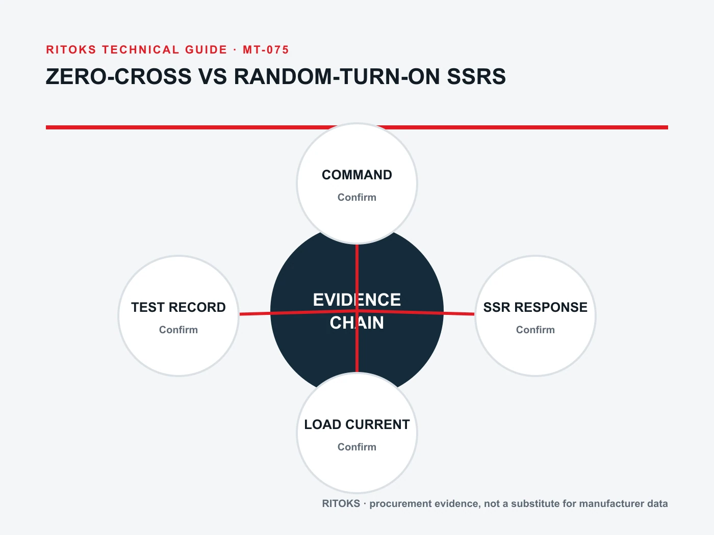
Normalize every Solid State Relay offer to the same application record. Keep document revisions, test conditions, included accessories and open questions beside each value. This makes differences in delivered scope visible and prevents a lower-cost but narrower offer from appearing equivalent to a complete solution.
Decision Workflow
- Freeze the application architecture and operating case.
- Record environmental, thermal and mechanical constraints.
- Identify the required Solid State Relay function without assuming a model.
- Request a complete order code and exact supporting documents.
- Compare every claim with its conditions and definitions.
- Resolve deviations and coordination questions before commercial approval.
- Archive the accepted evidence with the final bill of materials.
Stop the review when a critical application input is unknown, the quoted model is ambiguous, a required claim is supported only by another manufacturer or another order code, or the installation falls outside the available evidence. These are engineering gaps, not editorial details.
RFQ Preparation Checklist
A useful RFQ for zero crossing vs random turn on ssr is concise enough to answer and complete enough to prevent silent assumptions. Identify unknown values as questions and require a full orderable code rather than a generic family recommendation.
- Load behavior
- Turn-on objective
- Control method
- Switching cadence
- Thermal path
- Output type
- Trigger mode
- Leakage behavior
- Protection plan
- Exact datasheet
- Quantity, destination and required document language
Request the current datasheet revision and the exact scope of any certification, compatibility, coordination or performance claim. Record quantity and destination after the technical inputs so commercial terms do not obscure unresolved engineering questions.
Handoff From Engineering to Purchasing
Engineering approval should identify the exact Solid State Relay code, accepted document revisions, unresolved deviations and the application record used for the decision. Purchasing can then compare commercial offers without silently changing the technical basis. If a supplier proposes another code, different accessory or revised configuration, route it back through the same review instead of treating it as an administrative substitution.
Keep the approved evidence with the purchase order and final bill of materials. Receiving and production teams need enough information to recognize the accepted item and to stop when labeling, terminal arrangement, accessories or documentation differ. This handoff also gives maintenance teams a traceable starting point for replacement decisions rather than relying on a photograph, an old invoice description or one headline rating.
Frequently Asked Questions
Is zero-cross always better for resistive heating?
It may suit many on/off or burst-control heating duties, but the exact load, controller and model documentation still determine suitability.
Is random turn-on the same as phase-angle control?
No. Random turn-on describes relay response; a complete phase-related control system also requires a suitable controller and documented output behavior.
Can the same heatsink be used for any SSR of the same current?
No. Base losses, mounting, interface and ambient conditions must be calculated for the exact model.
Related RITOKS Products and Guidance
These links provide published product-family context only. A contextual link does not claim interchangeability, compatibility or an approved system combination.
Solid State Relay product category
Published RITOKS Solid State Relay product page
Related published RITOKS technical guide
Technical Reference
The following source supports only the general engineering concept stated in this guide. Its product ratings, circuit diagrams, approvals and coordination results do not transfer to RITOKS products.
Omron, Solid State Relays Technical Guide
Supports general distinctions among SSR switching behavior, load and thermal considerations; exact Omron values do not transfer to RITOKS products.
Request an Exact-Model Review
Send the application requirements, exact-document questions, quantity and destination through the RITOKS contact form. An RFQ requests an exact-model review; this guide does not approve a circuit, installation or automatic substitute.