
DIN Rail Energy Meters · Comparison
Single-Phase vs Three-Phase DIN Rail Energy Meters
A single phase vs three phase energy meter comparison begins with the circuit being measured. The first question is whether the measurement point is single-phase or three-phase, and which conductors are actually available. That decision changes the input architecture, wiring evidence and commissioning plan. A meter selected from a headline label alone can create an avoidable mismatch even when its display and rail mounting look familiar.
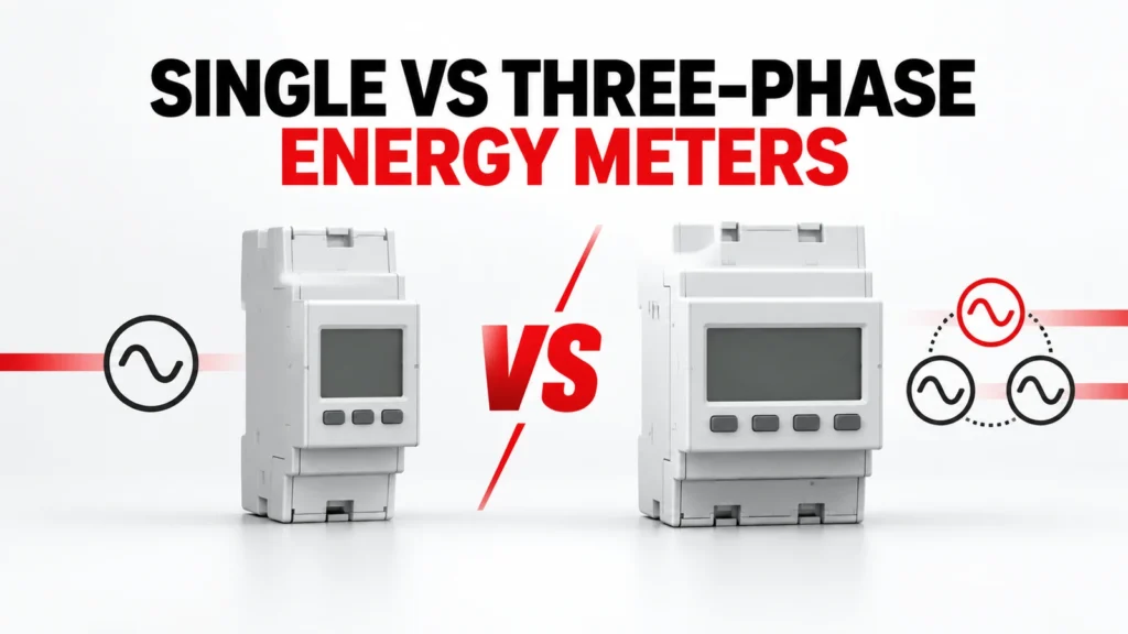
This guide compares the buying questions for single-phase and three-phase DIN rail energy meters. It keeps the meter type separate from direct versus transformer-connected measurement, communications and billing requirements. Each final choice must be supported by the exact meter diagram and order code.
Entscheidungsgrundlagen auf einen Blick
| Bewertungsbereich | Was der Käufer festhält | Anzufordernde Nachweise |
|---|---|---|
| System at measurement point | Document actual phase and neutral arrangement | Approved single-line diagram |
| Current input | Identify direct connection or transformer interface | Exact-meter input and wiring documentation |
| Ausgabe | Define displayed and exported data | Register map and interface document |
| Installation | Allow space, access and test points | Dimensioned drawing and commissioning plan |
Start at the measurement point
A site can contain both single-phase loads and a three-phase distribution system. The meter belongs to a specific measurement point, so describe the conductors and the circuit boundary there rather than naming only the upstream supply. A single-phase feeder serving one machine is a different metering problem from a three-phase feeder supplying a panel of mixed loads.
Provide a current single-line diagram, location of the meter, feeder identity, available conductors and the operational question the meter must answer. If one meter is expected to represent a group of circuits, show how those circuits enter the metering boundary.
What single-phase metering must establish
For a single-phase application, confirm the supply arrangement and the exact terminal path through or into the meter. A product described as single-phase does not establish whether it is direct connected, transformer connected, two-wire in the expected sense or suitable for every local circuit. The terminals, input limits and installation instructions govern.
A compact meter may be convenient for branch-circuit visibility, but the panel design still needs a suitable protective and isolation arrangement, conductor space and an accessible reading or communications method. Check those items in the assembly plan.
What three-phase metering adds
Three-phase energy measurement involves multiple voltage and current relationships. The wiring scheme must match the actual system arrangement, including whether a neutral is present and how the current inputs are obtained. A label such as three-phase is only the start of the specification.
Compare the exact meter wiring diagram with the panel single-line drawing. Mark each phase, current path and reference connection, and have the design team confirm that the selected scheme measures the intended feeder rather than a convenient subset of conductors.
Separate phase count from current interface
Phase count and current input method are separate decisions. A meter can have a direct-connected path or use external current transformers, depending on its design. The presence of a CT elsewhere in the panel does not prove the proposed meter accepts its secondary output or ratio setting.
If transformers are required, record their ratio, output, accuracy and burden evidence with the meter input specification. For a direct-connected option, review conductor routing, terminals and the specific permitted connection. Do not infer one interface from a neighboring model.
Define the data the project actually needs
Some projects need only a local energy reading. Others need interval data, alarms, pulse outputs or a network connection to a building or industrial system. These are independent requirements that may change the order code or wiring.
State the required measurements, update expectations, communication medium, register documentation and integration owner. A meter with a port is not automatically a working monitoring system: the receiving software must interpret the correct data and the commissioning team must verify the mapping.
Compare offers using one measurement brief
Ask each supplier to respond to the same measurement point, wiring architecture and data requirement. An offer for a single-phase branch meter is not equivalent to a three-phase feeder meter, even when both quote energy measurement. Likewise, a meter that needs external CTs is not a direct substitute for one designed for direct connection.
Record the complete meter code, accessories, transformer requirements, communications option and documents supplied. Keep differences visible instead of normalizing every quotation to a generic energy-meter line item.
Commission the actual installation
At commissioning, verify the connection against the approved diagram and check the sign and plausibility of measured values under known operating states. Compare the meter reading with the intended circuit boundary, not just with a powered display.
Where data is exported, confirm addressing, register interpretation, scaling and the destination system. Capture the configured parameters and as-built wiring so a replacement can be reviewed against the same evidence later.
Erstellen Sie eine Beweisdatei nach dem Exaktmodell
A category or product-family page helps locate relevant options; it does not by itself approve one variant. For DIN rail energy meters, keep the full proposed order code, current datasheet, terminal or mounting drawing, operating instructions and any project calculation together. Read the conditions attached to each rating or function. If the evidence belongs to a neighboring model, request the correct document instead of carrying the claim across.
Das Projektteam ist für die Systemvorgaben und Abnahmekriterien verantwortlich. Der Lieferant ist für die Nachweise zum angebotenen Produkt verantwortlich. Ordnen Sie bei der technischen Prüfung jede verbindliche Anforderung dem genauen Dokument und der jeweiligen Version zu, die diese erfüllt. Kennzeichnen Sie ein fehlendes Feld als „offen“, „bedingt“ oder „nicht unterstützt“. Dadurch entsteht eine nachvollziehbare Entscheidung und es wird verhindert, dass ein günstiger Nennwert eine inkompatible Verbindung oder Installationsbedingung verschleiert.
Vollständige Angebote vergleichen
| Artikel | Eintrag im Vergleich | Grund |
|---|---|---|
| Bestellbarer Artikel | Vollständige Artikelnummer, Variante und mitgeliefertes Zubehör | Verhindert Annahmen auf Familienebene |
| Anwendungsübereinstimmung | Schriftliche Stellungnahme zu jedem Projektbeitrag | Hält Ausnahmen sichtbar |
| Dokumentation | Datenblatt, Zeichnung, Anleitung und Überarbeitungen | Links zu Ansprüchen auf den angebotenen Artikel |
| Offene Punkte | Eigentümer und Fälligkeitsdatum zur Klärung | Verhindert stillschweigende Zustimmung |
Verwenden Sie für jedes Angebot dieselbe Projektbeschreibung. Kommerzielle Konditionen wie Preis und Lieferzeit lassen sich vergleichen, sobald der technische Umfang vereinheitlicht ist. Betrachten Sie ausgelassenes Zubehör, nicht unterstützte Nennleistungen oder eine ungeklärte Annahme zur Verkabelung nicht als gleichwertig mit einem dokumentierten Angebot. Wenn eine Alternative vorgeschlagen wird, fragen Sie nach, welche Eingaben sich ändern, und wiederholen Sie die betroffene Überprüfung.
Überprüfung der Installation und Abnahme
Vergewissern Sie sich vor der Installation, dass das mitgelieferte Etikett, der vollständige Code und das Zubehör mit den genehmigten Unterlagen übereinstimmen. Vergleichen Sie die Anschlüsse, die Befestigung, den Zugang zu den Leitern und die angegebene Ausrichtung mit den genauen Anweisungen. Ein Produkt, das äußerlich der genehmigten Version ähnelt, kann dennoch eine andere elektrische Konfiguration, Steuerungsoption oder Prüfgrundlage aufweisen.
Planen Sie eine Abnahmeprüfung, die auf die tatsächlichen Risiken des Projekts ausgerichtet ist. Dazu können unter anderem die Überprüfung der Verkabelung anhand des genehmigten Schaltplans, Funktionstests, Messungen unter repräsentativen Betriebsbedingungen sowie die Überprüfung aller Kommunikations- und Alarmfunktionen gehören. Halten Sie den Zustand und die Ergebnisse schriftlich fest. Der Abnahmeplan sollte sich aus den Anforderungen der Anwendung und den Nachweisen des Lieferanten ergeben und nicht auf einer allgemeinen Checkliste basieren.
Checkliste für Angebotsanfragen
- Identify the circuit, equipment and location that DIN rail energy meters must serve.
- Fügen Sie die Systemzeichnung und die Betriebszustände bei, die die Anwendung definieren.
- Record supply architecture and its source document.
- Leiter erfassen und deren Quelldokument.
- Record measurement point and its source document.
- Record meter input and its source document.
- Confirm the exact-model evidence for wiring diagram.
- Confirm the exact-model evidence for ct requirement.
- Confirm the exact-model evidence for data output.
- Confirm the exact-model evidence for commissioning.
- Bitte fordern Sie die vollständige Bestellnummer, das Zubehör, die Zeichnungen und die aktuelle Version des Datenblatts an.
- Erkundigen Sie sich nach Ausschlüssen, Annahmen, Ersatzlösungen und noch offenen technischen Fragen.
Die Angebotsanfrage sollte so konkret sein, dass ein Lieferant sie beantworten kann, ohne fehlende Projektwerte selbst zu erfinden. Wenn eine wesentliche Angabe noch nicht bekannt ist, kennzeichnen Sie diese als Frage und geben Sie an, wer sie festlegen wird. Machen Sie aus einer Annahme keine Bewertung, keine Konformitätserklärung und keine genehmigte Installationsmethode.
Was beeinflusst die Entscheidung?
A decision can change when the source arrangement, load behavior, environment, installation geometry or required function changes. Revisit the selected DIN rail energy meters whenever one of those inputs moves outside the approved brief. Recheck the order code and the exact evidence affected by the change; do not rely on a previous approval for a circuit that now asks the component to do different work.
Führen Sie ein kurzes Änderungsprotokoll über die Projektvorgabe, die Antwort des Lieferanten und die Liste der akzeptierten Ausnahmen. Diese Aufzeichnung hilft den Abteilungen Technik, Einkauf und Inbetriebnahme dabei, auf derselben Version zu arbeiten. Sie ist besonders nützlich, wenn ein Angebot überarbeitet wird, ein Ersatz angeboten wird oder sich die Schalttafelkonstruktion nach dem ersten Vergleich ändert.
Häufig gestellte Fragen
Can a three-phase meter replace a single-phase meter?
Only if the exact model documentation permits the intended single-phase wiring and the project accepts that configuration. Do not infer compatibility from the broader family name.
Does a meter with RS485 always support the required platform?
No. Obtain the exact protocol and register documentation, then test the intended points in the receiving system.
Are direct-connected and CT-operated meters interchangeable?
No. Their input arrangements and installation evidence differ. Match the meter and any CTs as one measured system.
Relevante RITOKS-Seiten
Informationen zum Kontext der Produktfamilie finden Sie unter Elektrische Messung und Überwachung. Zu den entsprechenden veröffentlichten Produktseiten gehören Dds1108 Single Phase Din Rail Energy Meter, Dts5158b Three Phase Four Wire Din Rail Energy Meter, 2p Single Phase Rs485 Modbus Din Rail Energy Meter. Verwenden Sie beim Vergleich eines vorgeschlagenen Artikels die aktuellen Unterlagen zum genauen Modell.
Für ein anwendungsspezifisches Angebot, Senden Sie die Projektbeschreibung an RITOKS mit den obenstehenden Diagrammen und offenen Fragen.