
DIN Rail Energy Meters · Comparison
Single-Phase vs Three-Phase DIN Rail Energy Meters
A single phase vs three phase energy meter comparison begins with the circuit being measured. The first question is whether the measurement point is single-phase or three-phase, and which conductors are actually available. That decision changes the input architecture, wiring evidence and commissioning plan. A meter selected from a headline label alone can create an avoidable mismatch even when its display and rail mounting look familiar.
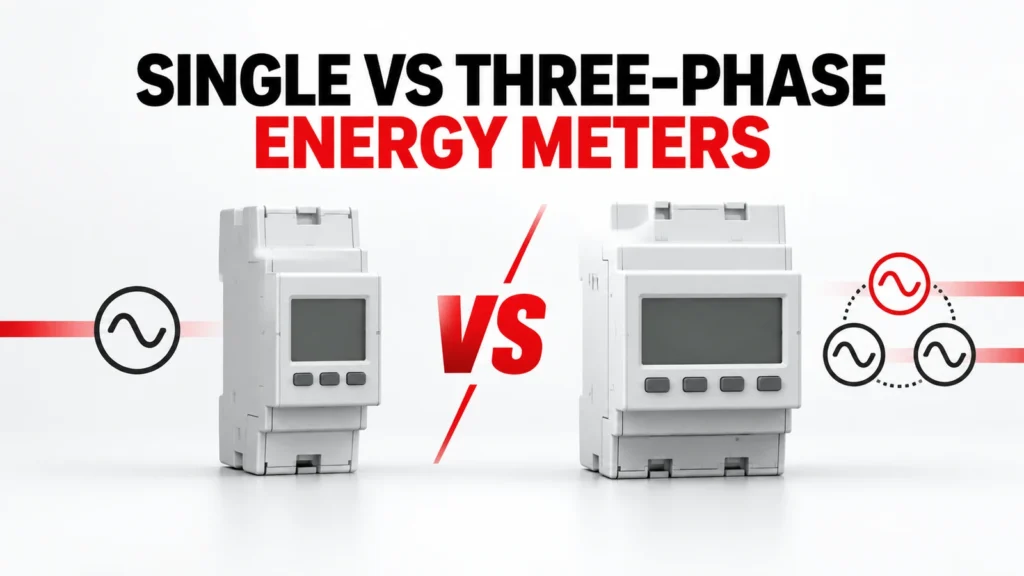
This guide compares the buying questions for single-phase and three-phase DIN rail energy meters. It keeps the meter type separate from direct versus transformer-connected measurement, communications and billing requirements. Each final choice must be supported by the exact meter diagram and order code.
Prezentare generală a datelor de intrare pentru luarea deciziilor
| Zona de evaluare | Ce înregistrează cumpărătorul | Documente care trebuie solicitate |
|---|---|---|
| System at measurement point | Document actual phase and neutral arrangement | Approved single-line diagram |
| Current input | Identify direct connection or transformer interface | Exact-meter input and wiring documentation |
| Rezultat | Define displayed and exported data | Register map and interface document |
| Instalare | Allow space, access and test points | Dimensioned drawing and commissioning plan |
Start at the measurement point
A site can contain both single-phase loads and a three-phase distribution system. The meter belongs to a specific measurement point, so describe the conductors and the circuit boundary there rather than naming only the upstream supply. A single-phase feeder serving one machine is a different metering problem from a three-phase feeder supplying a panel of mixed loads.
Provide a current single-line diagram, location of the meter, feeder identity, available conductors and the operational question the meter must answer. If one meter is expected to represent a group of circuits, show how those circuits enter the metering boundary.
What single-phase metering must establish
For a single-phase application, confirm the supply arrangement and the exact terminal path through or into the meter. A product described as single-phase does not establish whether it is direct connected, transformer connected, two-wire in the expected sense or suitable for every local circuit. The terminals, input limits and installation instructions govern.
A compact meter may be convenient for branch-circuit visibility, but the panel design still needs a suitable protective and isolation arrangement, conductor space and an accessible reading or communications method. Check those items in the assembly plan.
What three-phase metering adds
Three-phase energy measurement involves multiple voltage and current relationships. The wiring scheme must match the actual system arrangement, including whether a neutral is present and how the current inputs are obtained. A label such as three-phase is only the start of the specification.
Compare the exact meter wiring diagram with the panel single-line drawing. Mark each phase, current path and reference connection, and have the design team confirm that the selected scheme measures the intended feeder rather than a convenient subset of conductors.
Separate phase count from current interface
Phase count and current input method are separate decisions. A meter can have a direct-connected path or use external current transformers, depending on its design. The presence of a CT elsewhere in the panel does not prove the proposed meter accepts its secondary output or ratio setting.
If transformers are required, record their ratio, output, accuracy and burden evidence with the meter input specification. For a direct-connected option, review conductor routing, terminals and the specific permitted connection. Do not infer one interface from a neighboring model.
Define the data the project actually needs
Some projects need only a local energy reading. Others need interval data, alarms, pulse outputs or a network connection to a building or industrial system. These are independent requirements that may change the order code or wiring.
State the required measurements, update expectations, communication medium, register documentation and integration owner. A meter with a port is not automatically a working monitoring system: the receiving software must interpret the correct data and the commissioning team must verify the mapping.
Compare offers using one measurement brief
Ask each supplier to respond to the same measurement point, wiring architecture and data requirement. An offer for a single-phase branch meter is not equivalent to a three-phase feeder meter, even when both quote energy measurement. Likewise, a meter that needs external CTs is not a direct substitute for one designed for direct connection.
Record the complete meter code, accessories, transformer requirements, communications option and documents supplied. Keep differences visible instead of normalizing every quotation to a generic energy-meter line item.
Commission the actual installation
At commissioning, verify the connection against the approved diagram and check the sign and plausibility of measured values under known operating states. Compare the meter reading with the intended circuit boundary, not just with a powered display.
Where data is exported, confirm addressing, register interpretation, scaling and the destination system. Capture the configured parameters and as-built wiring so a replacement can be reviewed against the same evidence later.
Crearea unui dosar de probe bazat pe un model exact
A category or product-family page helps locate relevant options; it does not by itself approve one variant. For DIN rail energy meters, keep the full proposed order code, current datasheet, terminal or mounting drawing, operating instructions and any project calculation together. Read the conditions attached to each rating or function. If the evidence belongs to a neighboring model, request the correct document instead of carrying the claim across.
Echipa de proiect este responsabilă de datele de intrare ale sistemului și de criteriile de acceptare. Furnizorul este responsabil de dovezile referitoare la elementul oferit. În cadrul revizuirii tehnice, asociați fiecare cerință obligatorie cu documentul și versiunea exactă care răspund acesteia. Marcați un câmp lipsă ca fiind deschis, condiționat sau neacceptat. Astfel se creează o decizie trasabilă și se evită ca o valoare nominală favorabilă să ascundă o conexiune sau o condiție de instalare incompatibilă.
Compară ofertele complete
| Articol | Înregistrare în comparație | Motiv |
|---|---|---|
| Articol disponibil pentru comandă | Cod complet, variantă și accesorii incluse | Previne presupunerile la nivel de familie |
| Potrivire între aplicații | Răspuns scris la fiecare contribuție la proiect | Menține excepțiile vizibile |
| Documentație | Fișă tehnică, schiță, instrucțiuni și revizuiri | Legături cu privire la articolul oferit |
| Aspecte nerezolvate | Proprietar și termenul limită pentru clarificări | Evită acceptarea tacită |
Folosiți același caiet de sarcini pentru fiecare ofertă. Condițiile comerciale, precum prețul și termenul de livrare, pot fi comparate odată ce domeniul de aplicare tehnic este standardizat. Nu considerați accesoriile omise, valorile nominale nejustificate sau o ipoteză privind cablarea nerezolvată ca fiind echivalente cu o ofertă documentată. Dacă se propune o alternativă, întrebați care sunt elementele care se modifică și repetați analiza pentru elementele afectate.
Verificarea instalării și a recepției
Înainte de instalare, verificați dacă eticheta livrată, codul complet și accesoriile corespund cu înregistrarea aprobată. Comparați bornele, sistemul de montare, accesul la conductoare și orice orientare specificată cu instrucțiunile exacte. Un produs care pare similar din punct de vedere fizic cu versiunea aprobată poate avea totuși o configurație electrică, o opțiune de control sau o bază de testare diferită.
Planificați o verificare a stării la finalizare care să abordeze riscurile reale ale proiectului. Aceasta poate implica verificarea instalației electrice în raport cu schema aprobată, testarea funcționalității, efectuarea de măsurători în condiții reprezentative de funcționare și confirmarea funcționării tuturor sistemelor de comunicații sau de alarmă. Înregistrați starea și rezultatele. Planul de recepție trebuie să se bazeze pe documentația aplicației și pe dovezile furnizate de furnizor, nu pe o listă de verificare generică a componentelor.
Lista de verificare pentru cererea de ofertă
- Identify the circuit, equipment and location that DIN rail energy meters must serve.
- Atașați schița sistemului și stările de funcționare care definesc aplicația.
- Record supply architecture and its source document.
- Înregistrați conductorii și documentul sursă al acestora.
- Record measurement point and its source document.
- Record meter input and its source document.
- Confirm the exact-model evidence for wiring diagram.
- Confirm the exact-model evidence for ct requirement.
- Confirm the exact-model evidence for data output.
- Confirm the exact-model evidence for commissioning.
- Solicitați codul complet al comenzii, accesoriile, desenele tehnice și versiunea actualizată a fișei tehnice.
- Întrebați despre excepții, ipoteze, alternative și aspecte tehnice nerezolvate.
Cererea de ofertă trebuie să fie suficient de detaliată pentru ca un furnizor să poată răspunde fără a inventa valori lipsă din proiect. Dacă o informație esențială nu este încă cunoscută, marcați-o ca întrebare și precizați cine o va stabili. Nu transformați o ipoteză într-o evaluare, o declarație de conformitate sau o metodă de instalare aprobată.
Ce influențează decizia
A decision can change when the source arrangement, load behavior, environment, installation geometry or required function changes. Revisit the selected DIN rail energy meters whenever one of those inputs moves outside the approved brief. Recheck the order code and the exact evidence affected by the change; do not rely on a previous approval for a circuit that now asks the component to do different work.
Păstrați un istoric succint al reviziilor pentru caietul de sarcini al proiectului, răspunsul furnizorului și lista excepțiilor acceptate. Acest istoric ajută departamentele de inginerie, achiziții și punere în funcțiune să lucreze pe baza aceleiași versiuni. Este deosebit de util atunci când o ofertă este revizuită, se propune un produs înlocuitor sau proiectul panoului se modifică după prima comparație.
Întrebări frecvente
Can a three-phase meter replace a single-phase meter?
Only if the exact model documentation permits the intended single-phase wiring and the project accepts that configuration. Do not infer compatibility from the broader family name.
Does a meter with RS485 always support the required platform?
No. Obtain the exact protocol and register documentation, then test the intended points in the receiving system.
Are direct-connected and CT-operated meters interchangeable?
No. Their input arrangements and installation evidence differ. Match the meter and any CTs as one measured system.
Pagini relevante ale RITOKS
Pentru informații privind familia de produse, consultați Măsurarea și monitorizarea sistemelor electrice. Paginile de produs publicate pe această temă includ Dds1108 Single Phase Din Rail Energy Meter, Dts5158b Three Phase Four Wire Din Rail Energy Meter, 2p Single Phase Rs485 Modbus Din Rail Energy Meter. Folosiți documentele lor actuale referitoare la modelul exact atunci când comparați un articol propus.
Pentru o ofertă de preț adaptată aplicației dumneavoastră, trimiteți caietul de sarcini al proiectului către RITOKS împreună cu diagramele și întrebările deschise de mai sus.