
DIN Rail Energy Meters · Comparison
Single-Phase vs Three-Phase DIN Rail Energy Meters
A single phase vs three phase energy meter comparison begins with the circuit being measured. The first question is whether the measurement point is single-phase or three-phase, and which conductors are actually available. That decision changes the input architecture, wiring evidence and commissioning plan. A meter selected from a headline label alone can create an avoidable mismatch even when its display and rail mounting look familiar.
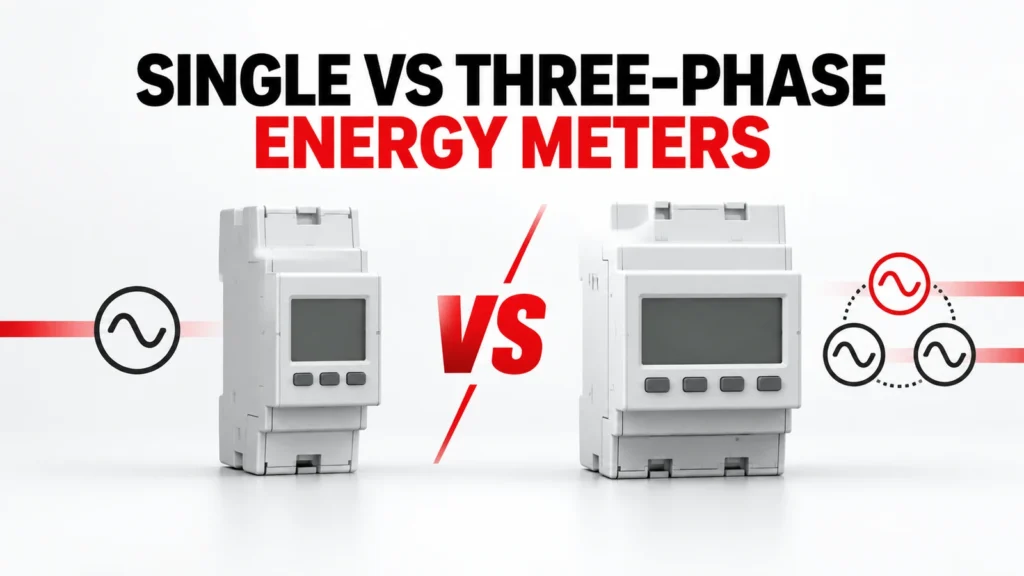
This guide compares the buying questions for single-phase and three-phase DIN rail energy meters. It keeps the meter type separate from direct versus transformer-connected measurement, communications and billing requirements. Each final choice must be supported by the exact meter diagram and order code.
Decision Inputs at a Glance
| Review area | What the buyer records | Evidence to request |
|---|---|---|
| System at measurement point | Document actual phase and neutral arrangement | Approved single-line diagram |
| Current input | Identify direct connection or transformer interface | Exact-meter input and wiring documentation |
| Output | Define displayed and exported data | Register map and interface document |
| Installation | Allow space, access and test points | Dimensioned drawing and commissioning plan |
Start at the measurement point
A site can contain both single-phase loads and a three-phase distribution system. The meter belongs to a specific measurement point, so describe the conductors and the circuit boundary there rather than naming only the upstream supply. A single-phase feeder serving one machine is a different metering problem from a three-phase feeder supplying a panel of mixed loads.
Provide a current single-line diagram, location of the meter, feeder identity, available conductors and the operational question the meter must answer. If one meter is expected to represent a group of circuits, show how those circuits enter the metering boundary.
What single-phase metering must establish
For a single-phase application, confirm the supply arrangement and the exact terminal path through or into the meter. A product described as single-phase does not establish whether it is direct connected, transformer connected, two-wire in the expected sense or suitable for every local circuit. The terminals, input limits and installation instructions govern.
A compact meter may be convenient for branch-circuit visibility, but the panel design still needs a suitable protective and isolation arrangement, conductor space and an accessible reading or communications method. Check those items in the assembly plan.
What three-phase metering adds
Three-phase energy measurement involves multiple voltage and current relationships. The wiring scheme must match the actual system arrangement, including whether a neutral is present and how the current inputs are obtained. A label such as three-phase is only the start of the specification.
Compare the exact meter wiring diagram with the panel single-line drawing. Mark each phase, current path and reference connection, and have the design team confirm that the selected scheme measures the intended feeder rather than a convenient subset of conductors.
Separate phase count from current interface
Phase count and current input method are separate decisions. A meter can have a direct-connected path or use external current transformers, depending on its design. The presence of a CT elsewhere in the panel does not prove the proposed meter accepts its secondary output or ratio setting.
If transformers are required, record their ratio, output, accuracy and burden evidence with the meter input specification. For a direct-connected option, review conductor routing, terminals and the specific permitted connection. Do not infer one interface from a neighboring model.
Define the data the project actually needs
Some projects need only a local energy reading. Others need interval data, alarms, pulse outputs or a network connection to a building or industrial system. These are independent requirements that may change the order code or wiring.
State the required measurements, update expectations, communication medium, register documentation and integration owner. A meter with a port is not automatically a working monitoring system: the receiving software must interpret the correct data and the commissioning team must verify the mapping.
Compare offers using one measurement brief
Ask each supplier to respond to the same measurement point, wiring architecture and data requirement. An offer for a single-phase branch meter is not equivalent to a three-phase feeder meter, even when both quote energy measurement. Likewise, a meter that needs external CTs is not a direct substitute for one designed for direct connection.
Record the complete meter code, accessories, transformer requirements, communications option and documents supplied. Keep differences visible instead of normalizing every quotation to a generic energy-meter line item.
Commission the actual installation
At commissioning, verify the connection against the approved diagram and check the sign and plausibility of measured values under known operating states. Compare the meter reading with the intended circuit boundary, not just with a powered display.
Where data is exported, confirm addressing, register interpretation, scaling and the destination system. Capture the configured parameters and as-built wiring so a replacement can be reviewed against the same evidence later.
Build an Exact-Model Evidence File
A category or product-family page helps locate relevant options; it does not by itself approve one variant. For DIN rail energy meters, keep the full proposed order code, current datasheet, terminal or mounting drawing, operating instructions and any project calculation together. Read the conditions attached to each rating or function. If the evidence belongs to a neighboring model, request the correct document instead of carrying the claim across.
The project team owns the system inputs and acceptance criteria. The supplier owns the evidence for the offered item. In the technical review, place each mandatory requirement beside the exact document and revision that answers it. Mark a missing field as open, conditional or unsupported. This creates a traceable decision and prevents a favorable headline value from hiding an incompatible connection or installation condition.
Compare Complete Offers
| Item | Record in the comparison | Reason |
|---|---|---|
| Orderable item | Full code, variant and included accessories | Prevents family-level assumptions |
| Application match | Written response to each project input | Keeps exceptions visible |
| Documentation | Datasheet, drawing, instructions and revisions | Links claims to the offered item |
| Open points | Owner and due date for clarification | Avoids silent acceptance |
Use the same project brief for every quotation. Commercial terms such as price and lead time can be compared once the technical scope is normalized. Do not treat omitted accessories, unsupported ratings or an unresolved wiring assumption as equivalent to a documented offer. If an alternative is proposed, ask which inputs change and repeat the affected review.
Review Installation and Acceptance
Before installation, confirm that the delivered label, complete code and accessories match the approved record. Compare terminals, mounting, conductor access and any stated orientation with the exact instructions. A product that appears physically similar to the approved version may still have a different electrical configuration, control option or test basis.
Plan an as-built check that addresses the project's real risks. This may involve wiring against the approved diagram, functional response, measurements under representative operating states and confirmation of any communication or alarm feature. Record the conditions and results. The acceptance plan should come from the application and supplier evidence, not from a generic article checklist.
Request for Quotation Checklist
- Identify the circuit, equipment and location that DIN rail energy meters must serve.
- Attach the system drawing and operating states that define the application.
- Record supply architecture and its source document.
- Record conductors and its source document.
- Record measurement point and its source document.
- Record meter input and its source document.
- Confirm the exact-model evidence for wiring diagram.
- Confirm the exact-model evidence for ct requirement.
- Confirm the exact-model evidence for data output.
- Confirm the exact-model evidence for commissioning.
- Request the full order code, accessories, drawings and data-sheet revision.
- Ask for exclusions, assumptions, substitutes and unresolved engineering points.
The RFQ should be specific enough for a supplier to answer without inventing missing project values. If an essential input is not yet known, label it as a question and identify who will determine it. Do not turn an assumption into a rating, a compliance claim or an approved installation method.
What Changes the Decision
A decision can change when the source arrangement, load behavior, environment, installation geometry or required function changes. Revisit the selected DIN rail energy meters whenever one of those inputs moves outside the approved brief. Recheck the order code and the exact evidence affected by the change; do not rely on a previous approval for a circuit that now asks the component to do different work.
Keep a short revision history of the project brief, supplier response and accepted exception list. This record helps engineering, purchasing and commissioning work from the same version. It is especially useful when a quotation is revised, a substitute is offered or the panel design changes after the first comparison.
Frequently Asked Questions
Can a three-phase meter replace a single-phase meter?
Only if the exact model documentation permits the intended single-phase wiring and the project accepts that configuration. Do not infer compatibility from the broader family name.
Does a meter with RS485 always support the required platform?
No. Obtain the exact protocol and register documentation, then test the intended points in the receiving system.
Are direct-connected and CT-operated meters interchangeable?
No. Their input arrangements and installation evidence differ. Match the meter and any CTs as one measured system.
Relevant RITOKS Pages
For product-family context, see Electrical Measurement & Monitoring. The related published product pages include Dds1108 Single Phase Din Rail Energy Meter, Dts5158b Three Phase Four Wire Din Rail Energy Meter, 2p Single Phase Rs485 Modbus Din Rail Energy Meter. Use their current exact-model documents when comparing a proposed item.
For an application-specific quotation, send the project brief to RITOKS with the diagrams and open questions above.