
DIN Rail Energy Meters · Comparison
Single-Phase vs Three-Phase DIN Rail Energy Meters
A single phase vs three phase energy meter comparison begins with the circuit being measured. The first question is whether the measurement point is single-phase or three-phase, and which conductors are actually available. That decision changes the input architecture, wiring evidence and commissioning plan. A meter selected from a headline label alone can create an avoidable mismatch even when its display and rail mounting look familiar.
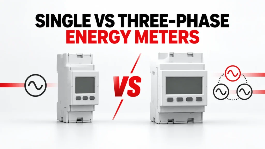
This guide compares the buying questions for single-phase and three-phase DIN rail energy meters. It keeps the meter type separate from direct versus transformer-connected measurement, communications and billing requirements. Each final choice must be supported by the exact meter diagram and order code.
Podsumowanie danych wejściowych do decyzji
| Obszar przeglądu | Co odnotowuje nabywca | Dokumenty, o których udostępnienie należy wystąpić |
|---|---|---|
| System at measurement point | Document actual phase and neutral arrangement | Approved single-line diagram |
| Current input | Identify direct connection or transformer interface | Exact-meter input and wiring documentation |
| Wynik | Define displayed and exported data | Register map and interface document |
| Instalacja | Allow space, access and test points | Dimensioned drawing and commissioning plan |
Start at the measurement point
A site can contain both single-phase loads and a three-phase distribution system. The meter belongs to a specific measurement point, so describe the conductors and the circuit boundary there rather than naming only the upstream supply. A single-phase feeder serving one machine is a different metering problem from a three-phase feeder supplying a panel of mixed loads.
Provide a current single-line diagram, location of the meter, feeder identity, available conductors and the operational question the meter must answer. If one meter is expected to represent a group of circuits, show how those circuits enter the metering boundary.
What single-phase metering must establish
For a single-phase application, confirm the supply arrangement and the exact terminal path through or into the meter. A product described as single-phase does not establish whether it is direct connected, transformer connected, two-wire in the expected sense or suitable for every local circuit. The terminals, input limits and installation instructions govern.
A compact meter may be convenient for branch-circuit visibility, but the panel design still needs a suitable protective and isolation arrangement, conductor space and an accessible reading or communications method. Check those items in the assembly plan.
What three-phase metering adds
Three-phase energy measurement involves multiple voltage and current relationships. The wiring scheme must match the actual system arrangement, including whether a neutral is present and how the current inputs are obtained. A label such as three-phase is only the start of the specification.
Compare the exact meter wiring diagram with the panel single-line drawing. Mark each phase, current path and reference connection, and have the design team confirm that the selected scheme measures the intended feeder rather than a convenient subset of conductors.
Separate phase count from current interface
Phase count and current input method are separate decisions. A meter can have a direct-connected path or use external current transformers, depending on its design. The presence of a CT elsewhere in the panel does not prove the proposed meter accepts its secondary output or ratio setting.
If transformers are required, record their ratio, output, accuracy and burden evidence with the meter input specification. For a direct-connected option, review conductor routing, terminals and the specific permitted connection. Do not infer one interface from a neighboring model.
Define the data the project actually needs
Some projects need only a local energy reading. Others need interval data, alarms, pulse outputs or a network connection to a building or industrial system. These are independent requirements that may change the order code or wiring.
State the required measurements, update expectations, communication medium, register documentation and integration owner. A meter with a port is not automatically a working monitoring system: the receiving software must interpret the correct data and the commissioning team must verify the mapping.
Compare offers using one measurement brief
Ask each supplier to respond to the same measurement point, wiring architecture and data requirement. An offer for a single-phase branch meter is not equivalent to a three-phase feeder meter, even when both quote energy measurement. Likewise, a meter that needs external CTs is not a direct substitute for one designed for direct connection.
Record the complete meter code, accessories, transformer requirements, communications option and documents supplied. Keep differences visible instead of normalizing every quotation to a generic energy-meter line item.
Commission the actual installation
At commissioning, verify the connection against the approved diagram and check the sign and plausibility of measured values under known operating states. Compare the meter reading with the intended circuit boundary, not just with a powered display.
Where data is exported, confirm addressing, register interpretation, scaling and the destination system. Capture the configured parameters and as-built wiring so a replacement can be reviewed against the same evidence later.
Stwórz plik dowodów oparty na modelu dokładnym
A category or product-family page helps locate relevant options; it does not by itself approve one variant. For DIN rail energy meters, keep the full proposed order code, current datasheet, terminal or mounting drawing, operating instructions and any project calculation together. Read the conditions attached to each rating or function. If the evidence belongs to a neighboring model, request the correct document instead of carrying the claim across.
Zespół projektowy odpowiada za dane wejściowe systemu i kryteria odbioru. Dostawca odpowiada za dokumentację potwierdzającą zgodność oferowanego produktu. Podczas przeglądu technicznego należy przyporządkować każde obowiązkowe wymaganie do konkretnego dokumentu i wersji, które je spełniają. Brakujące pole należy oznaczyć jako otwarte, warunkowe lub nieobsługiwane. Pozwala to na śledzenie podjętych decyzji i zapobiega sytuacji, w której korzystna wartość nominalna maskuje niezgodność połączenia lub warunków instalacji.
Porównaj pełne oferty
| Pozycja | Wpis w zestawieniu porównawczym | Powód |
|---|---|---|
| Produkt dostępny w sprzedaży | Pełny kod, wariant i dołączone akcesoria | Zapobiega wyciąganiu wniosków na poziomie rodziny |
| Zgodność aplikacji | Pisemna odpowiedź na każdy wkład w projekt | Zapewnia widoczność wyjątków |
| Dokumentacja | Arkusz danych technicznych, rysunek, instrukcje i aktualizacje | Powiązania z oferowanym przedmiotem |
| Kwestie do rozstrzygnięcia | Właściciel i termin, w którym należy udzielić wyjaśnień | Pozwala uniknąć milczącej zgody |
W każdej ofercie należy stosować ten sam opis projektu. Warunki handlowe, takie jak cena i czas realizacji, można porównać dopiero po ujednoliceniu zakresu technicznego. Nie należy traktować pominiętych akcesoriów, niepotwierdzonych parametrów technicznych ani nierozstrzygniętych założeń dotyczących okablowania jako równoważnych z udokumentowaną ofertą. Jeśli zaproponowano alternatywę, należy zapytać, które dane wejściowe ulegają zmianie, i powtórzyć przegląd elementów, których to dotyczy.
Przegląd instalacji i odbioru
Przed montażem należy sprawdzić, czy dostarczona etykieta, pełny kod i akcesoria są zgodne z zatwierdzoną dokumentacją. Należy porównać zaciski, sposób montażu, dostęp do przewodów oraz wszelkie określone orientacje z dokładnymi instrukcjami. Produkt, który wygląda podobnie do wersji zatwierdzonej, może mimo to mieć inną konfigurację elektryczną, opcję sterowania lub podstawę testową.
Należy zaplanować kontrolę zgodności z projektem wykonawczym, która uwzględni rzeczywiste zagrożenia związane z projektem. Może to obejmować sprawdzenie zgodności okablowania z zatwierdzonym schematem, testy funkcjonalne, pomiary w reprezentatywnych warunkach eksploatacyjnych oraz weryfikację działania wszelkich funkcji komunikacyjnych i alarmowych. Należy odnotować stan i wyniki. Plan odbioru powinien opierać się na dokumentacji aplikacji i dowodach dostawcy, a nie na ogólnej liście kontrolnej.
Lista kontrolna dotycząca zapytania ofertowego
- Identify the circuit, equipment and location that DIN rail energy meters must serve.
- Należy dołączyć rysunek schematu systemu oraz stany pracy, które określają zastosowanie.
- Record supply architecture and its source document.
- Zarejestruj przewodniki wraz z dokumentami źródłowymi.
- Record measurement point and its source document.
- Record meter input and its source document.
- Confirm the exact-model evidence for wiring diagram.
- Confirm the exact-model evidence for ct requirement.
- Confirm the exact-model evidence for data output.
- Confirm the exact-model evidence for commissioning.
- Proszę o przesłanie pełnego kodu zamówienia, akcesoriów, rysunków oraz aktualnej wersji karty katalogowej.
- Zapytaj o wyjątki, założenia, rozwiązania zastępcze oraz nierozstrzygnięte kwestie techniczne.
Zapytanie ofertowe powinno być na tyle szczegółowe, aby dostawca mógł na nie odpowiedzieć bez konieczności domyślania się brakujących danych dotyczących projektu. Jeśli jakaś istotna informacja nie jest jeszcze znana, należy oznaczyć ją jako pytanie i wskazać, kto ją ustali. Nie należy traktować założenia jako kryterium oceny, oświadczenia o zgodności ani zatwierdzonej metody montażu.
Co wpływa na podjęcie decyzji
A decision can change when the source arrangement, load behavior, environment, installation geometry or required function changes. Revisit the selected DIN rail energy meters whenever one of those inputs moves outside the approved brief. Recheck the order code and the exact evidence affected by the change; do not rely on a previous approval for a circuit that now asks the component to do different work.
Należy prowadzić krótką historię zmian dotyczącą opisu projektu, odpowiedzi dostawcy oraz listy zaakceptowanych wyjątków. Dokumentacja ta ułatwia działom inżynierii, zaopatrzenia i uruchomienia pracę w oparciu o tę samą wersję. Jest to szczególnie przydatne w przypadku zmiany oferty, zaproponowania zamiennika lub modyfikacji projektu szafy sterowniczej po pierwszym porównaniu.
Najczęściej zadawane pytania
Can a three-phase meter replace a single-phase meter?
Only if the exact model documentation permits the intended single-phase wiring and the project accepts that configuration. Do not infer compatibility from the broader family name.
Does a meter with RS485 always support the required platform?
No. Obtain the exact protocol and register documentation, then test the intended points in the receiving system.
Are direct-connected and CT-operated meters interchangeable?
No. Their input arrangements and installation evidence differ. Match the meter and any CTs as one measured system.
Odpowiednie strony serwisu RITOKS
Aby zapoznać się z informacjami dotyczącymi rodziny produktów, zobacz Pomiary i monitorowanie instalacji elektrycznych. Powiązane opublikowane strony produktów obejmują: Dds1108 Single Phase Din Rail Energy Meter, Dts5158b Three Phase Four Wire Din Rail Energy Meter, 2p Single Phase Rs485 Modbus Din Rail Energy Meter. Podczas porównywania proponowanego produktu należy korzystać z aktualnych dokumentów dotyczących dokładnie tego samego modelu.
Aby otrzymać ofertę dostosowaną do konkretnego zastosowania, prześlij brief projektowy do firmy RITOKS wraz z powyższymi schematami i otwartymi pytaniami.